Advertisement
Advertisement
Table of Contents

Summary of Contents for Rupert Neve Designs Shelford
- Page 1 Shelford Diode Bridge Compressor Operations Manual Operations Manual...
-
Page 2: Important Safety Instructions
CAUTION: Changes or modifications to this device not expressly 11. Only use attachments/accessories specified by the manufacturer. approved by Rupert Neve Designs LLC, could void the user's authority to 12. Use only with a cart, stand, tripod, bracket, or PORTABLE CART operate the equipment under FCC rules. - Page 3 Table of Contents Introduction Block Diagram Front Panel Rear Panel Shelford Compressor Features Specifications Limited Warranty...
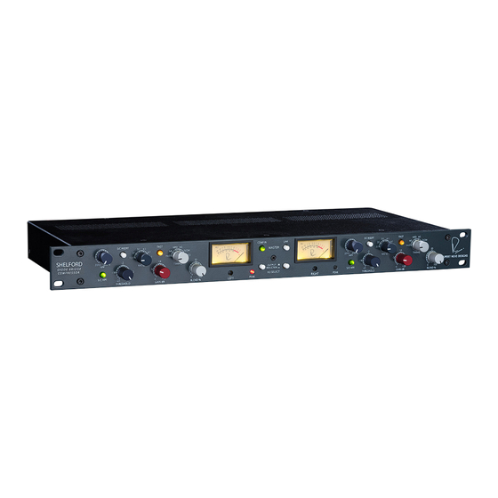
- Page 4 Rupert Neve Designs: Shelford Diode Bridge Compressor Thank you for purchasing the Rupert Neve Designs Shelford Diode Bridge Compressor. We hope you enjoy using this product as much as we have enjoyed designing and building it. The Shelford Compressor features custom Rupert Neve Designs transformer-coupled inputs and outputs, Class-A analog signal paths, and full-wave rectifi- cation in the compressor sidechain.
- Page 7 Shelford Compressor Front Panel Features THRESHOLD The THRESHOLD control is a 31-detent potentiometer that allows the user to adjust the point at which compres- sion occurs, between -25dBu and +20dBu. Turning this control counter-clockwise will increase the amount of compression; turning it clockwise will decrease the amount of compression. If the input signal is lower than the set threshold, no compression will occur.
- Page 8 Shelford Compressor Front Panel Features (continued) S/C INSERT This push-button switch enables the S/C INSERT SEND and RETURN jacks on the rear-panel of the compressor. This allows the user to patch in additional external processing gear into the compressor side-chain (such as an external EQ).
-
Page 9: Line Input
IEC standard 3-pin grounded AC power inlet with power switch. 100-240VAC 50/60Hz input range with a maxi- mum power consumption of 45W. LINE INPUT Neutrik XLR combo jack line input utilizing custom Rupert Neve Designs transformer-coupled, balanced inputs. Maximum input signal level is +26.7 dBu at 1kHz. LINE OUTPUT Neutrik XLR jack line output utilizing custom Rupert Neve Designs transformer-coupled, balanced outputs. - Page 10 Shelford Compressor Specifications XLR Line Input to XLR Line Output (Compressor Bypassed) = 40 Ω Balanced SOURCE Input Impedance 10 kΩ Output Impedance 40 Ω Maximum Input Level (+4 dBu Selected) +26.7 dBu typical Maximum Output Level +26.7 dBu typical...
- Page 11 Shelford Compressor Ratio RMS Level Sweep...
-
Page 12: Product Warranty
PRODUCT WARRANTY Rupert Neve Designs warrants this product to be free from defects in materials and workmanship for a period of three (3) years from date of purchase, and agrees to remedy any defect identified within such three year period by, at our option, repairing or replacing the product.


Need help?
Do you have a question about the Shelford and is the answer not in the manual?
Questions and answers