Table of Contents
Advertisement
Quick Links
Advertisement
Table of Contents

Related Manuals for FISCHER MS10


Summary of Contents for FISCHER MS10
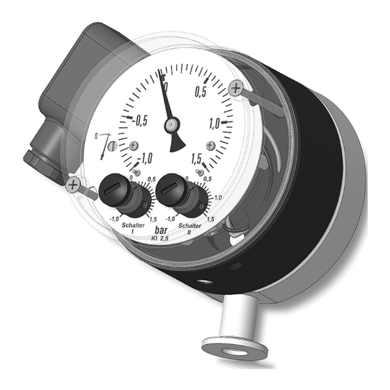
- Page 1 Operating manual MS10 Pressure vacuum switch...
- Page 2 Great care was taken when compiling the texts and illustrations; Nevertheless, errors cannot be ruled out. The company FISCHER Mess- und Regeltechnik GmbH will not accept any legal responsibility or liability for this.
-
Page 3: Table Of Contents
FISCHER Mess- und Regeltechnik GmbH Table of contents Table of contents 1 Safety instructions......................4 1.1 General........................... 1.2 Personnel Qualification ......................1.3 Risks due to Non-Observance of Safety Instructions............. 1.4 Safety Instructions for the Operating Company and the Operator ......... -
Page 4: Safety Instructions
1 | Safety instructions FISCHER Mess- und Regeltechnik GmbH 1 Safety instructions 1.1 General This operating manual contains basic instructions for the installation, operation and maintenance of the device that must be followed without fail. It must be read by the installer, the operator and the responsible specialist personnel be- fore installing and commissioning the device. -
Page 5: Safe Working Practices For Maintenance And Installation Work
FISCHER Mess- und Regeltechnik GmbH Safety instructions | 1 1.7 Safe working practices for maintenance and installation work The safety instructions given in this operating manual, any nationally applicable regulations on accident prevention and any of the operating company's internal work, operating and safety guidelines must be observed. -
Page 6: Product And Functional Description
Circuit diagram Serial number 2.3 Intended use The MS10 is an overpressure and vacuum-pressure proof contact pressure gauge for control and monitoring tasks in vacuum technology. The device may only be used for the purpose stipulated by the manufacturer. The manufacturer will not be liable for damage arising from incorrect or im- proper use. -
Page 7: Function Diagram
FISCHER Mess- und Regeltechnik GmbH Product and functional description | 2 2.4 Function diagram Fig. 2: Function diagram Measuring capsule Hydraulic fluid Pressure chamber Motion train Tappet Micro-switch Sealing plug Process connection 2.5 Design and mode of operation The measuring element is a measuring capsule with two metal diaphragms that are hydraulically coupled. -
Page 8: Installation
3 | Installation FISCHER Mess- und Regeltechnik GmbH 3 Installation The MS10 is equipped for pipeline installation with a small flange ISO KF10 in accordance with DIN 28403 or ISO 2861. The device was calibrated for vertical installation. To ensure safety during installation and maintenance, we recommend installing a suitable shut-off valve on the system. - Page 9 FISCHER Mess- und Regeltechnik GmbH Installation | 3 Cable socket can be mounted offset by 180° cable screw connection Fig. 4: Cable socket Terminals 1 to 6 Brass Screw terminal up to 1.5 mm Ground terminal Nickel-plated brass Screw terminal up to 2.5 mm...
-
Page 10: Start-Up
4 | Start-up FISCHER Mess- und Regeltechnik GmbH 4 Start-up A prerequisite for commissioning is correct installation of all electrical supply lines and the pressure lines. All connections are arranged so that there are no mechanical forces acting on the device. -
Page 11: Switch Point Adjustment
FISCHER Mess- und Regeltechnik GmbH Start-up | 4 4.2 Switch point adjustment Proceed as follows to set the switching points: 1. Remove the plug in the hood. Sealing plug 1.2 x 7 Seal 2. You can now set the desired switching point with a suitable screwdriver us- ing the switching point reference value scales. -
Page 12: Servicing
5 | Servicing FISCHER Mess- und Regeltechnik GmbH 5 Servicing 5.1 Maintenance The instrument is maintenance-free. We recommend the following regular in- spection to guarantee reliable operation and a long service life: • Check the function in combination with downstream components. -
Page 13: Technical Data
FISCHER Mess- und Regeltechnik GmbH Technical data | 6 6 Technical data 6.1 General Information Reference conditions (acc. to IEC 61298-1) Temperature +15 … +25 °C Relative humidity 45 … 75% Air pressure 86 to 106 kPa 860 to 1060 mbar... -
Page 14: Output Parameters
6 | Technical data FISCHER Mess- und Regeltechnik GmbH 6.3 Output parameters Switch contacts 1 to 2 micro-switches Switching function (per contact) Changeover contact Switch point setting Can be set to reference scales from outside Smallest settable value approx 5% of the measuring span Switch hysteresis approx 2.5% of the measuring span... - Page 15 FISCHER Mess- und Regeltechnik GmbH Technical data | 6 6.5.2 Dimensional drawings All dimensions in mm unless otherwise stated Small flange ISO KF10 Fig. 7: Dimension drawing BA_EN_MS10 15/20...
-
Page 16: Order Codes
7 | Order codes FISCHER Mess- und Regeltechnik GmbH 7 Order codes Code no. 10 11 12 Type [1.2] Measuring range -200 … 200 mbar 0 … 400 mbar -1 … 0.6 -1 … 1.5 -1 … 3 -1 … 5 -1 …... -
Page 17: Annex
FISCHER Mess- und Regeltechnik GmbH Annex | 8 8 Annex Fig. 8: CE_DE_MS10 BA_EN_MS10 17/20... - Page 18 8 | Annex FISCHER Mess- und Regeltechnik GmbH Fig. 9: Module B 18/20 BA_EN_MS10...
- Page 19 FISCHER Mess- und Regeltechnik GmbH Annex | 8 BA_EN_MS10 19/20...
- Page 20 Mess- und Regeltechnik GmbH Bielefelder Str. 37a D-32107 Bad Salzuflen Tel. +49 5222 974-0 Fax +49 5222 7170 www.fischermesstechnik.de info@fischermesstechnik.de Technische Änderungen vorbehalten. Subject to technical changes. Sous réserve de modifications techniques.
Need help?
Do you have a question about the MS10 and is the answer not in the manual?
Questions and answers