Table of Contents
Advertisement
Quick Links
Advertisement
Table of Contents

Related Manuals for FISCHER DS13


Summary of Contents for FISCHER DS13
- Page 1 IEC 61508 Operating manual DS13 Differential pressure switch...
- Page 2 Great care was taken when compiling the texts and illustrations; Nevertheless, errors cannot be ruled out. The company FISCHER Mess- und Regeltechnik GmbH will not accept any legal responsibility or liability for this.
-
Page 3: Table Of Contents
FISCHER Mess- und Regeltechnik GmbH Table of contents Table of contents 1 Safety instructions......................4 1.1 General........................... 1.2 Personnel Qualification ......................1.3 Risks due to Non-Observance of Safety Instructions............. 1.4 Safety Instructions for the Operating Company and the Operator ......... -
Page 4: Safety Instructions
1 | Safety instructions FISCHER Mess- und Regeltechnik GmbH 1 Safety instructions 1.1 General This operating manual contains basic instructions for the installation, operation and maintenance of the device that must be followed without fail. It must be read by the installer, the operator and the responsible specialist personnel be- fore installing and commissioning the device. -
Page 5: Safe Working Practices For Maintenance And Installation Work
FISCHER Mess- und Regeltechnik GmbH Safety instructions | 1 1.7 Safe working practices for maintenance and installation work The safety instructions given in this operating manual, any nationally applicable regulations on accident prevention and any of the operating company's internal work, operating and safety guidelines must be observed. -
Page 6: Product And Functional Description
2 | Product and functional description FISCHER Mess- und Regeltechnik GmbH 2 Product and functional description 2.1 Delivery scope • Differential pressure switch DS13 • Operating Manual 2.2 Equipment versions 2.2.1 Pressure chamber Aluminium Stainless steel Fig. 1: Material options for the pressure chamber 2.2.2 Electrical connection... -
Page 7: Intended Use
Product and functional description | 2 2.3 Intended use The DS13 is a switching device for differential pressure, over and under-pres- sure for gaseous and fluid media. This series is ideally suited for various meas- uring tasks in rough environments. -
Page 8: Assembly
3 | Assembly FISCHER Mess- und Regeltechnik GmbH 3 Assembly 3.1 General The device is designed for wall mounting. NOTICE! At the factory, the device is calibrated for vertical installation and only this installation position is allowed. To ensure safety during installation and maintenance, we recommend installing a suitable shut-off valve on the system (see accessories). - Page 9 FISCHER Mess- und Regeltechnik GmbH Assembly | 3 Fluid media Settable reactor pins below the closing cap G¼ Fig. 6: Controllable damping reactor MZ40 In the operational status, the reactor pins need to be set so that the measure- ment display follows the pressure changes with a delay.
-
Page 10: Start-Up
4 | Start-up FISCHER Mess- und Regeltechnik GmbH 4 Start-up 4.1 General All electrical supply, operating and measuring lines, and the pressure connec- tions must have been correctly installed before commissioning. All supply lines are arranged so that there are no mechanical forces acting on the device. -
Page 11: Switch Point Setting
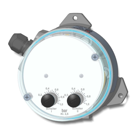
FISCHER Mess- und Regeltechnik GmbH Start-up | 4 4.4 Switch point setting 1.2 x 8 Switch point setting Fig. 10: Switch point setting 1. Remove the plugs (1) and the seals (2) in the hood and/or open the bayonet ring enclosure. -
Page 12: Servicing
5 | Servicing FISCHER Mess- und Regeltechnik GmbH 5 Servicing 5.1 Maintenance The instrument is maintenance-free. We recommend the following regular in- spection to guarantee reliable operation and a long service life: • Check the function in combination with downstream components. -
Page 13: Technical Data
FISCHER Mess- und Regeltechnik GmbH Technical data | 6 6 Technical data 6.1 General Information Reference conditions (acc. to IEC 61298-1) Temperature +15 … +25 °C Relative humidity 45 … 75 % Air pressure 86 … 106 kPa 860 … 1060 mbar... -
Page 14: Operating Conditions
6 | Technical data FISCHER Mess- und Regeltechnik GmbH 6.4 Operating conditions Increase ambient temperature -10 … +70 °C Media temperature -10 … +70 °C Storage temperature -15 … +75 °C Enclosure protection class IP55 as per EN 60529 EN 61010-1:2010... - Page 15 FISCHER Mess- und Regeltechnik GmbH Technical data | 6 Parts with no contact with the medium Cover hood IP55 Makrolon Bayonet ring housing IP65 Stainless steel 1.4301 Dial face and needle Aluminium Setting buttons AlCuMgPb 3.1645 6.5.2 Dimensional drawings All dimensions in mm unless otherwise stated The following are the dimensional diagrams for the pressure chambers in alu- minium.
- Page 16 6 | Technical data FISCHER Mess- und Regeltechnik GmbH Process connection variants Ø5 Ø21 Ø9.5 Internal thread G¼ Fig. 12: Process connection G¼ G¼ ØD DIN EN 837 Cutting ring Connecting shanks d1 G¼B G½B 17,5 Cutting ring screw connection ØD...
-
Page 17: Order Codes
FISCHER Mess- und Regeltechnik GmbH Order Codes | 7 7 Order Codes Code no. 10 11 12 13 Type Optional information e.g. SIL Measuring diaphragm [1.2] Measuring range NBR / VITON Inconel 718 0 … 250 mbar 0 … 400 mbar 0 …... - Page 18 7 | Order Codes FISCHER Mess- und Regeltechnik GmbH [5.6] Process connection Material Inner thread G¼ Inner thread ¼-18 NPT Connection shanks with external thread G¼ B Brass Connection shanks with external thread G¼ B CrNi steel Connecting port G½ with outer thread ¼-18...
- Page 19 DZ11 Installation set for retrofitting from wall mounting to switch panel in- stallation. Please state the precise device type of the DS13 because there are different switch panel installation sets depending on the model. DZ23/24 The shut-off valve DZ23 in a three spindle model and DZ24 in a four spindle model can be particularly beneficial when mounting the differ- ential pressure measuring and switch device DS13.
-
Page 20: Attachments
8 | Attachments FISCHER Mess- und Regeltechnik GmbH 8 Attachments 8.1 SIL Certificate Fig. 13: SIL_4479913759902 20/24 BA_EN_DS13... - Page 21 FISCHER Mess- und Regeltechnik GmbH Attachments | 8 Fig. 14: SIL_4479913759902 BA_EN_DS13 21/24...
- Page 22 8 | Attachments FISCHER Mess- und Regeltechnik GmbH 8.2 EU Declaration of Conformity Fig. 15: CE_DE_DS13 22/24 BA_EN_DS13...
- Page 23 FISCHER Mess- und Regeltechnik GmbH Attachments | 8 8.3 UKCA Declaration of Conformity Fig. 16: UKCA_EN_DS13 BA_EN_DS13 23/24...
- Page 24 Mess- und Regeltechnik GmbH Bielefelder Str. 37a D-32107 Bad Salzuflen Tel. +49 5222 974-0 Fax +49 5222 7170 www.fischermesstechnik.de info@fischermesstechnik.de Technische Änderungen vorbehalten. Subject to technical changes. Sous réserve de modifications techniques.
Need help?
Do you have a question about the DS13 and is the answer not in the manual?
Questions and answers