Table of Contents
Advertisement
Quick Links
Advertisement
Table of Contents

Related Manuals for FISCHER DS31


Summary of Contents for FISCHER DS31
- Page 1 Operating manual DS31 Differential pressure switch...
- Page 2 Great care was taken when compiling the texts and illustrations; Nevertheless, errors cannot be ruled out. The company FISCHER Mess- und Regeltechnik GmbH will not accept any legal responsibility or liability for this.
-
Page 3: Table Of Contents
FISCHER Mess- und Regeltechnik GmbH Table of contents Table of contents 1 Safety instructions ......................4 1.1 General........................... 1.2 Personnel Qualification......................1.3 Risks due to Non-Observance of Safety Instructions ............. 1.4 Safety Instructions for the Operating Company and the Operator ......... -
Page 4: Safety Instructions
1 | Safety instructions FISCHER Mess- und Regeltechnik GmbH 1 Safety instructions 1.1 General This operating manual contains basic instructions for the installation, operation and maintenance of the device that must be followed without fail. It must be read by the installer, the operator and the responsible specialist personnel be- fore installing and commissioning the device. -
Page 5: Safe Working Practices For Maintenance And Installation Work
FISCHER Mess- und Regeltechnik GmbH Safety instructions | 1 1.7 Safe working practices for maintenance and installation work The safety instructions given in this operating manual, any nationally applicable regulations on accident prevention and any of the operating company's internal work, operating and safety guidelines must be observed. -
Page 6: Product And Functional Description
One scale and a setting mark attached to the type plate show the respectively set switch-point. 2.3 Intended use The DS31 is a differential pressure switch for overpressure, underpressure and differential pressure measurements. The uncomplicated and durable membrane measuring mechanism is suitable for neutral fluid media, e.g. service water, heating water, neutral gases and oils. -
Page 7: Product Summary
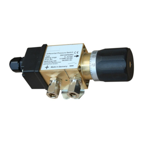
FISCHER Mess- und Regeltechnik GmbH Product and functional description | 2 2.5 Product summary Fig. 2: Product summary Connection cable Cable screw connection Cover hood Pressure chamber Mounting foot Scale Setting button Cutting ring screw connection Type plate 2.5.1 Process connection As standard, the device has a process connection G⅛... -
Page 8: Assembly
3 | Assembly FISCHER Mess- und Regeltechnik GmbH 3 Assembly 3.1 General The device is intended for installation on flat walls and mounting plates. The device has a mounting foot for screwing to the mounting plate. 3.2 Process connection • By authorized and qualified specialized personnel only. -
Page 9: Electrical Connections
FISCHER Mess- und Regeltechnik GmbH Assembly | 3 CAUTION Maximum tightening torque The maximum torque for the G⅛ inch inner thread is 5 Nm. The cutting ring screw connections may only be mounted with counter brackets. Preparation • Assembly is only possible with tubes that are cut off at right angles. The usual tolerances for minimum tube length, angle and chamber apply. - Page 10 3 | Assembly FISCHER Mess- und Regeltechnik GmbH With permanently wired numbered cables Optionally, a numbered cable (see order code) is permanently wired. The cable numbers correspond to the numbers of the terminals. 10/20 BA_EN_DS31...
-
Page 11: Start-Up
FISCHER Mess- und Regeltechnik GmbH Start-up | 4 4 Start-up 4.1 General A prerequisite for commissioning is correct installation of all electrical supply lines and the differential pressure lines. All connections are arranged so that there are no mechanical forces acting on the device. -
Page 12: Servicing
5 | Servicing FISCHER Mess- und Regeltechnik GmbH 5 Servicing 5.1 Maintenance The instrument is maintenance-free. We recommend the following regular in- spection to guarantee reliable operation and a long service life: • Check the function in combination with downstream components. -
Page 13: Technical Data
FISCHER Mess- und Regeltechnik GmbH Technical data | 6 6 Technical data 6.1 General Reference conditions (acc. to IEC 61298-1) Temperature +15 to +25 °C Relative humidity 45 … 75 % Air pressure 86 to 106 kPa 860 to 1060 mbar... -
Page 14: Operating Conditions
6 | Technical data FISCHER Mess- und Regeltechnik GmbH 6.6 Operating conditions Ambient temperature range -10 to +70 °C Storage temperature range -10 to +80 °C Medium temperature range -10 to +80 °C (for non-freezing media) Low-Voltage Directive EN 61010-1:2010 +A1:2019+A1:2019/... - Page 15 FISCHER Mess- und Regeltechnik GmbH Technical data | 6 ØD2 ØD1 Fig. 8: Cutting ring screw connection ØD1 ØD2 A/F 1 A/F 2 G⅛ 6 mm 14 mm 8 mm 23.5 mm 14 mm 14 mm G⅛ 8 mm 14 mm 8 mm 24.5 mm...
-
Page 16: Order Codes
7 | Order codes FISCHER Mess- und Regeltechnik GmbH 7 Order codes Code no. Type [1.2] Measuring range Adjustment range 0 to 400 mbar 4 to 400 mbar 0 to 0.6 bar 0.06 to 0.6 bar 0 to 1 bar 0.10 to 1.0 bar... -
Page 17: Attachment
FISCHER Mess- und Regeltechnik GmbH Attachment | 8 8 Attachment Fig. 10: CE_DE_DS31 BA_EN_DS31 17/20... - Page 18 FISCHER Mess- und Regeltechnik GmbH 18/20 BA_EN_DS31...
- Page 19 FISCHER Mess- und Regeltechnik GmbH BA_EN_DS31 19/20...
- Page 20 Mess- und Regeltechnik GmbH Bielefelder Str. 37a D-32107 Bad Salzuflen Tel. +49 5222 974-0 Fax +49 5222 7170 www.fischermesstechnik.de info@fischermesstechnik.de Technische Änderungen vorbehalten. Subject to technical changes. Sous réserve de modifications techniques.
Need help?
Do you have a question about the DS31 and is the answer not in the manual?
Questions and answers