Table of Contents
Advertisement
Quick Links
d e v e l o p i n g
s o l u t i o n s
User Manual
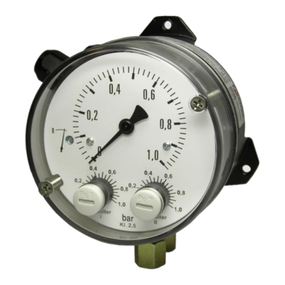
DS11
Differential pressure switch
Contents
1
Safety guidelines
2
3
4
5
6
7
8
9
1
Safety guidelines
1.1
General
This operating manual contains instruc-
tions fundamental to the installation,
operation and maintenance of the de-
vice that must be observed uncondi-
tionally. It must be read by the fitter, the operator
and the responsible technical personnel before in-
stallation and commissioning of the device.
This operating manual is an integral part of the
product and therefore needs to be kept close to the
instrument in a place that is accessible at all times
to the responsible personnel.
The following sections, in particular instructions
about the assembly, commissioning and mainte-
nance,
contain
important
observance of which could pose a threat to hu-
mans, animals, the environment and property.
1.2
Personnel Qualification
The device may only be installed and commis-
sioned by specialized personnel familiar with the in-
stallation, commissioning and operation of this
product.
Specialized personnel are persons who can assess
the work they have been assigned and recognize
potential dangers by virtue of their specialized train-
ing, their skills and experience and their knowledge
of the pertinent standards.
information,
non-
1.3
Risks due to Non-Observance of Safe-
ty Instructions
Non-observance of these safety instructions, the in-
tended use of the device or the limit values given in
the technical specifications can be hazardous or
cause harm to persons, the environment or the
plant itself.
The supplier of the equipment will not be liable for
damage claims if this should happen.
1.4
Safety Instructions for the Operating
Company and the Operator
The safety instructions governing correct operation
of the instrument must be observed. The operating
company must make them available to the installa-
tion, maintenance, inspection and operating per-
sonnel.
Dangers arising from electrical components, energy
discharged by the medium, escaping medium and
incorrect installation of the device must be eliminat-
ed. See the information in the applicable national
and international regulations.
1.5
Unauthorized Modification
Modifications of or other technical alterations to the
instrument by the customer are not permitted. This
also applies to replacement parts. Only
the manufacturer is authorized to make
any modifications or changes.
Advertisement
Table of Contents

Subscribe to Our Youtube Channel
Related Manuals for FISCHER DS11


Summary of Contents for FISCHER DS11
-
Page 1: Table Of Contents
User Manual DS11 Differential pressure switch Contents Safety guidelines Application purpose Product and functional description Installation and assembly Commissioning Maintenance and Repeat Tests... -
Page 2: Application Purpose
Inadmissible Modes of Operation Product and functional description The operational safety of this instrument can only Function diagram be guaranteed if it is used as intended. The instru- ment model must be suitable for the medium used in the system. The limit values given in the technical data may not be exceeded. - Page 3 valve on the system (see accessories section). This 4.1.2 Pressure surge absorption means that Pulsating pressure on the system side can lead to the device can be depressurized or taken out of wear and functional problems. To safeguard this, operation we recommend installing absorption elements in the pressure pipe line.
-
Page 4: Commissioning
• The electrical connection of the device shall be Control Elements performed according to relevant VDE and local electricity board regulations. Zero-point correction screw • Disconnect the system from the mains before connecting the device. • Add a fuse adapted to the energy requirements. 4.2.1 Cable socket and plug connection Ground connection... -
Page 5: Maintenance And Repeat Tests
5.4.2 Testing when the system is operational Service A measurement is shown. If despite operational All defective or faulty devices should be sent direct- pressure, no measurement is shown, you can gen- ly to our repair department. Please coordinate all erate a differential pressure by blocking the differ- shipments with our sales department. -
Page 6: Technical Data
11 Technical data General points -10 … +70 °C Admissible ambient temperature -10 … +70 °C Admissible media temperature -15 … +75 °C Admissible storage temperature Enclosure protection class IP55 acc. to DIN EN 60529 1.2 kg (Pressure chamber in aluminium) Weight 3.5 kg (Pressure chamber in stainless steel 1.4305) Measuring system... -
Page 7: Dimensional Drawings
12 Dimensional drawings (all dimensions in mm unless otherwise specified) M16x1.5 plastic screw connection Cutting ring screw connection DS11 Wall mounting (Standard model) SW19 Cable connection socket or 7-pin plug connection Connection Connection spigot M20x1.5 Cable screw connection G¼ inner thread G¼... -
Page 8: Order Codes
13 Order Codes Differential pressure measuring and switching device Type DS11 Max. stat. operating Measuring range pressure 0 …400 .. mbar ............6 bar ......> 0 … 0.6 .. bar ............10 bar ......> 0 … 1 .. bar ............ - Page 9 13.1 Accessories DZ11 Control panel installation set Ø 132, comprising a front ring, distance columns and at- tachment screws. DZ13/14 The shutoff and equalization valves DZ13/14 in three and four spindle versions are highly suitable when mounting differential pressure devices. The following can be used for ex- ample: •...
-
Page 10: Manufacturer's Declarations And Certificates
14 Manufacturer's Declarations and Certificates 14.1 EC Declaration of conformity 10 | 16 Page... - Page 11 14.2 Certificate functional security SIL2 11 | 16 Page...
- Page 12 12 | 16 Page...
- Page 13 14.3 GL approval 13 | 16 Page...
- Page 14 14 | 16 Page...
- Page 15 15 | 16 Page...
- Page 16 Technische Änderungen vorbehalten • Subject to change without notice • Changements techniques sous réserve Fischer Mess- und Regeltechnik GmbH • Bielefelder Str. 37a • D-32107 Bad Salzuflen • Tel. +49 5222 9740 • Fax +49 5222 7170 eMail: info@fischermesstechnik.de • www.fischermesstechnik.de...
Need help?
Do you have a question about the DS11 and is the answer not in the manual?
Questions and answers