
Subscribe to Our Youtube Channel
Related Manuals for FISCHER DS 11


Summary of Contents for FISCHER DS 11
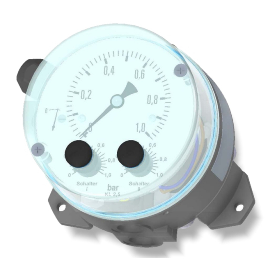
- Page 1 IEC 61508 SIL2 Operating manual DS11 Differential pressure measuring and switching device...
- Page 2 Great care was taken when compiling the texts and illustrations; Nevertheless, errors cannot be ruled out. The company FISCHER Mess- und Regeltechnik GmbH will not accept any legal responsibility or liability for this.
-
Page 3: Table Of Contents
FISCHER Mess- und Regeltechnik GmbH Table of contents Table of contents 1 Safety instructions ......................4 1.1 General........................... 1.2 Personnel Qualification......................1.3 Risks due to Non-Observance of Safety Instructions ............. 1.4 Safety Instructions for the Operating Company and the Operator ......... -
Page 4: Safety Instructions
1 | Safety instructions FISCHER Mess- und Regeltechnik GmbH 1 Safety instructions 1.1 General This operating manual contains basic instructions for the installation, operation and maintenance of the device that must be followed without fail. It must be read by the installer, the operator and the responsible specialist personnel be- fore installing and commissioning the device. -
Page 5: Safe Working Practices For Maintenance And Installation Work
FISCHER Mess- und Regeltechnik GmbH Safety instructions | 1 1.7 Safe working practices for maintenance and installation work The safety instructions given in this operating manual, any nationally applicable regulations on accident prevention and any of the operating company's internal work, operating and safety guidelines must be observed. -
Page 6: Product And Functional Description
2 | Product and functional description FISCHER Mess- und Regeltechnik GmbH 2 Product and functional description 2.1 Delivery scope • Differential pressure measuring and switching device DS11 • Operating Manual 2.2 Equipment versions 2.2.1 Pressure chamber Aluminium Stainless steel Fig. 1: Material options for the pressure chamber 2.2.2 Assembly... - Page 7 FISCHER Mess- und Regeltechnik GmbH Product and functional description | 2 2.2.3 Protection class Pressure chamber in aluminium Pressure chamber in stainless steel Fig. 3: Protection class IP65 2.2.4 Electrical connection Number cable Cable socket/plug connection Fig. 4: Options for the electrical connection 2.2.5 Type plate...
-
Page 8: Intended Use
2 | Product and functional description FISCHER Mess- und Regeltechnik GmbH 2.3 Intended use The DS11 is a combined display and switching device for differential pressure, over and under-pressure for gaseous and fluid media. This series is ideally suited for various measuring tasks in rough environments. -
Page 9: Assembly
FISCHER Mess- und Regeltechnik GmbH Assembly | 3 3 Assembly 3.1 General The device is designed for wall mounting. Optionally, the device can also be supplied with an installed switch panel set. NOTICE! At the factory, the device is calibrated for vertical installation and only this installation position is allowed. - Page 10 3 | Assembly FISCHER Mess- und Regeltechnik GmbH Fluid media Settable reactor pins below the closing cap G¼ Fig. 8: Controllable damping reactor In the operational status, the reactor pins need to be set so that the measure- ment display follows the pressure changes with a delay.
-
Page 11: Electrical Connections
FISCHER Mess- und Regeltechnik GmbH Assembly | 3 3.3 Electrical connections • By authorized and qualified specialized personnel only. • When connecting the unit, the national and international electro-technical regulations must be observed. • Disconnect the system from the mains, before electrically connecting the device. - Page 12 3 | Assembly FISCHER Mess- und Regeltechnik GmbH 3.3.2 Plug connection can be mounted offset by 180° Cable screw connection Fig. 12: Cable plug Terminals 1 to 6 Brass Screw terminal up to 1.5 mm Ground terminal Cable screw connec- Polyamide 6 M20x1.5...
-
Page 13: Start-Up
FISCHER Mess- und Regeltechnik GmbH Start-up | 4 4 Start-up 4.1 General All electrical supply, operating and measuring lines, and the pressure connec- tions must have been correctly installed before commissioning. All supply lines are arranged so that there are no mechanical forces acting on the device. -
Page 14: Zero Point Correction
4 | Start-up FISCHER Mess- und Regeltechnik GmbH 4.3.2 Enclosure with protection class IP65 Ø100 1. Release the bayonet ring (1) by turning to the left. if the bayonet ring cannot be opened by hand, use a pipe wrench (4). -
Page 15: Function Test
FISCHER Mess- und Regeltechnik GmbH Start-up | 4 4.6 Function test Remove both plugs in the hood for testing or open the bayonet ring enclosure. If the unit has two micro-switches, the stated test steps must be carried out for both switches. -
Page 16: Servicing
5 | Servicing FISCHER Mess- und Regeltechnik GmbH 5 Servicing 5.1 Maintenance The instrument is maintenance-free. We recommend the following regular in- spection to guarantee reliable operation and a long service life: • Check the function in combination with downstream components. -
Page 17: Technical Data
FISCHER Mess- und Regeltechnik GmbH Technical data | 6 6 Technical data 6.1 General Information Reference conditions (acc. to IEC 61298-1) Temperature +15 … +25 °C Relative humidity 45 … 75 % Air pressure 86 … 106 kPa 860 … 1060 mbar... -
Page 18: Output Parameters
6 | Technical data FISCHER Mess- und Regeltechnik GmbH 6.3 Output parameters Switch contacts 1 to 2 micro-switches Switching function (per contact) Changeover contact Switch point setting Can be set to reference scales from outside Smallest settable value 5% of the upper range value Switch hysteresis 2.5% of the upper range value... - Page 19 FISCHER Mess- und Regeltechnik GmbH Technical data | 6 6.5.1 Materials Parts in contact with the me- dium Pressure chamber Aluminium GkAlSi10(mg); painted black © Aluminium GkALSi10(mg); HART-COAT surface protection Chromium nickel steel 1.4305 Chromium nickel steel 1.4571 Measuring diaphragm ®...
- Page 20 6 | Technical data FISCHER Mess- und Regeltechnik GmbH 6.5.2 Dimensional drawings All dimensions in mm unless otherwise stated The following are the dimensional diagrams for the different models of the pres- sure chambers in aluminium. The dimensional diagrams for the pressure cham- bers in stainless steel are similar.
- Page 21 FISCHER Mess- und Regeltechnik GmbH Technical data | 6 Process connection variants G¼ G¼ ØD DIN EN 837 Cutting ring Connecting shanks d1 G¼B G½B 17.5 Cutting ring screw connection ØD Pipe diameter 6, 8, 10 G¼ NPT outside Connecting shanks N NPT outside ¼-18 NPT 42...
-
Page 22: Order Codes
7 | Order Codes FISCHER Mess- und Regeltechnik GmbH 7 Order Codes Code no. 11 12 13 14 15 16 17 Type Optional information e.g. SIL Measuring diaphragm [1.2] Measuring range NBR / VITON Inconel 718 0 … 250 mbar 0 …... - Page 23 FISCHER Mess- und Regeltechnik GmbH Order Codes | 7 [5.6] Process connection Material Inner thread G¼ Inner thread ¼-18 NPT Connection shanks with external thread G¼ B Brass Connection shanks with external thread G¼ B CrNi steel Connecting port G½ with outer thread ¼-18...
- Page 24 7 | Order Codes FISCHER Mess- und Regeltechnik GmbH Accessories Please go to our website fischermesstechnik.de for data sheets for the measur- ing device accessories. DZ11 Installation set for retrofitting from wall mounting to switch panel in- stallation. Please state the precise device type of the DS11 because there are different switch panel installation sets depending on the model.
-
Page 25: Attachments
FISCHER Mess- und Regeltechnik GmbH Attachments | 8 8 Attachments 8.1 SIL Certificate Fig. 17: SIL_4479913759902 BA_EN_DS11... - Page 26 8 | Attachments FISCHER Mess- und Regeltechnik GmbH Fig. 18: SIL_4479913759902 BA_EN_DS11...
- Page 27 FISCHER Mess- und Regeltechnik GmbH Attachments | 8 8.2 DNV-GL Certificate Fig. 19: DNV-GL_TAA00002BW_(1) BA_EN_DS11...
- Page 28 8 | Attachments FISCHER Mess- und Regeltechnik GmbH Fig. 20: DNV-GL_TAA00002BW_(2) BA_EN_DS11...
- Page 29 FISCHER Mess- und Regeltechnik GmbH Attachments | 8 Fig. 21: DNV-GL_TAA00002BW_(3) BA_EN_DS11...
- Page 30 8 | Attachments FISCHER Mess- und Regeltechnik GmbH 8.3 EU Declaration of Conformity Fig. 22: CE_DE_DS11 BA_EN_DS11...
- Page 31 ÜCHOBHOH rocyJ:(apcrneHHblH perncTpaUHOHHblH HOMep: 1037739575125, TenectioH: +7 495 725-23-09, aJ:(pec B JIHIJ,e feHepanbHOro J:(HpeKTopa Waposa AneKcaHJ:(pa AHaTOnheBJ. I qa 1aHBJIHeT, 'ITO ,ll; M ctJctJepeHUHaJihHhIH MaHoMeTp c nepeKnJOqaTeneM, THn DS2 l , DS 11 H1roTOBHTeJih "FISCHER Mess- und Regeltechnik GmbH" MecTO HaXO:>KJ:(eHJ.151: Bielefelder StraBe 37a, D-32107 Bad Salzuflen, repMaHH.SI.
- Page 32 Mess- und Regeltechnik GmbH Bielefelder Str. 37a D-32107 Bad Salzuflen Tel. +49 5222 974-0 Fax +49 5222 7170 www.fischermesstechnik.de info@fischermesstechnik.de Technische Änderungen vorbehalten. Subject to technical changes. Sous réserve de modifications techniques.
Need help?
Do you have a question about the DS 11 and is the answer not in the manual?
Questions and answers