
Related Manuals for Global LPZ 9912


Summary of Contents for Global LPZ 9912
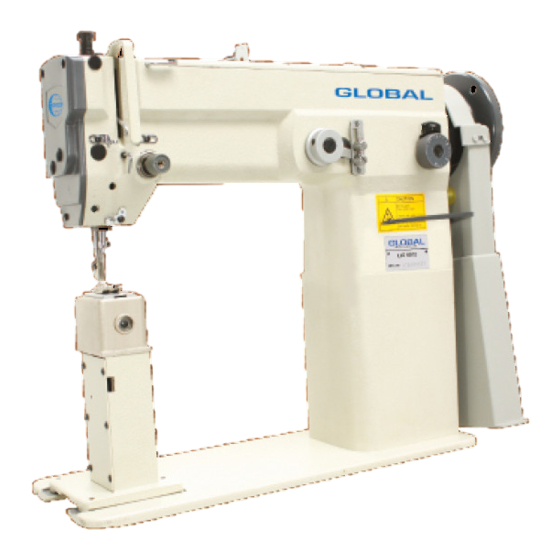
- Page 1 GLOBAL LPZ 9912 / 9912-H Instruction & parts manual www .globalsew .corn info@globalsew.com...
-
Page 3: Safety Instructions
Before use your new machine, please read the safety instructions below and the explanations given in the instruction manual. With industrial sewing machines, it is normal to carry out work while positioned directly in front of moving pads such as the needle and thread take-up.and consequently there is always a danger of injury that can be caused by these port. -
Page 4: Note On Safety
± 2.Note on safety AcAUTION Environmental requirements Use the sewing machine in an area which is The relative humidity should be within the free from sources of strong electrical noise range of45%-85% during use , and no dew fomiation should occur in any devices. such as high-frequency welders. - Page 5 ACAUTION Sewing Attach all safety devices befori> This sewing machine should only be used by using the sewing machine. operators who have received the necessary If the machine is used without these training in safe use beforehand. devices attached, injury rnay result. The sewing machine should not be used for Do not touch any of the moving parts or any applications other than sewing.
- Page 7 INDEX · - : · -· · - · · - ·· · ··· · · · ·· ·- - Upper shaft m echa n is m - · · · · · · -· · - · - · • · · ·...
- Page 8 � � 1 2 � - 1 5, 3 2 8 ___.(iJ 1 6 , 3 3 2 , 3 1 � � � � c::, � � �� � � � � :n � --,,_, .-,, , .: = �...
- Page 9 A.Machine body ( 1 = LP 9912 2 = LP 9912 H) BH 1 0-006 /n4• l0xfi PB810028 1452A-23 15301\-002 :3702-901 :{702 029 1 l. Hx5 1 5/6 1 2Hx7 PB810-027 ()i) 10. 8x4 :3702-005 > Pl5.8x6 :3700A-027 P8. 8x5 PB8l(H)l9 29 3700A-{l29 PB8 IO- I 09...
-
Page 10: Stitch Regulator Mechanism
Stitch regulator mechanism B.Upper shaft mechanism �-- 1 4 - � i -·- -· -·- _j -·-·- - -·· - .J -·- m¼) -·--·- - · · r - � 13 : • L •• - - - --�� ���� --�-� - ��; 1�... - Page 11 C. Stitch regulator mechanism ( J) B. Upper shaft mechanis m 1 = LP 9912 2 = LP 9912 H 153013-023 1 1 /64--40x:l. 5 1530B -00 l 1530LH)02 0341C-060 I l/61--; 1 0x4 1530B003 PB810 l0.IS l/4-t0x6 1 s:rnB-O(M PB8 l0--l 16 I 5:HJl3005 ( 1)
- Page 12 ' F eed mechanism & D.Needle bar rocking lower shaft mechanism � 3 � - -- 3 1 � - 29 ' 20...
- Page 13 15:30C--029 ( 1 = LP 9912 2 = LP 9912H) l l/64- l0x6 ��6 D. Needle bar rocking & lower shaft mechanism 1530(·001 1530C--026 1530C-027 15:WC-002 9910,1-002 �M-0. 75x1 l 530C-·028 l 5:lOC-004 1 s: 3 oc--o:rn f3810 006 l l/64-40x4 W5xl0xl W5xl0xl ��41C--060...
-
Page 14: G.presser Foot Mechanism
F.Feed mechanism G.Presser foot mechanism... -
Page 15: P Resser Foot Mechanism
-·8- F .• Feed mechanism 1 = LP 9912 2 = LP 9912 H) P\ 3 810-226 1530E-001 1530E-018 J 530E ·002 1530E-019 1452F3 3:300D-2348 5:30E-006 06 I 3300D-234C PB8 I0·222 ll/64-40x7 W6xl0 PB810-109 ��300D-234A Pf3810-068 11 /64-40x 1 :� l530E-024 S-15 J5/64-28xll... - Page 16 H.Upper f d ee mechanism 5 - - i �� "· "' � ©� --" ··-...
- Page 17 H. ( Upper feed LP 9912 H) 9HIOC-017 M5x6 '. 1 708·· l94A i>nfl l O 008 ll/64·· 4 0 x 6 :! l ()'.) :�70 8 I5:: i :l 2 :noo[·0:{2 ():\ PB810-027 J:-i/64 28x7 3700E O(M (),1 M6x20 J700E-O:M ! ,10x1fi PB810 21:ilS...
-
Page 18: Name Of Major Parts
I.Name of major parts 1. Need plate 2. Face plate 10. Reverse lever 3. Thread take-up 11. Bobbin winder assy 4. Oil window 12. Belt coverassy 5. Cottonstand assy 13. Cover .K-Lifter plate 6. Pully 14. Stitch length dial assy 7. - Page 19 J.Machine specifications LP 9912 LP 9912 H � l450spm 1200spm Speed Zigzag width DPx5 0Px5. Needle size -------- Thead take-up capacity 73mm 73mm Needle bar capacity 31mm 31mm Presser foot operating �l-7mm Presser foot tising rate 7nun 7nun Shuttle Big shuttle Big shuttle Medium-weight materials to Light-weight materials to...
- Page 20 As figure (3) shown: Fix the hinge seats® and the support rubbers@>0supplien whit the machine on table using nails® Then push &in the oil pan As figure ( shown: Head hingeOpush the machine. Tap the head rest securely into the table hole.
-
Page 21: Installing The Needle
K. Adjustment Installing the.needle As figure (6-1 6-Z)shown: Rotate handwheel to make needle bar rise to the meximumhigh,loosen tighten screw @plug needle Oto the top needle's groove side face to A then fsten screw@. (6-2) (6-1) As figure (7) shown: <1 >... -
Page 22: Presser Foot Pressure Adjustment
As figure ( 9) shown: < > Threading the upper thread lnsent the upper thread Oas figure shown, <2> Face line tension adjustment Rotate clipper8, the upperline tension in direction Xincrease and Y direction decrease • Presser foot pressure adjustment As figure shown: (10) -
Page 23: Troubleshoot
P. TROUBLESHOOT Corrective measures when Trouble parse What Trouble Correct direction from Wrong direction of Direction and height. of high to maximum high upper needle needle Change needle needle Bend needle Adjust l'eed dog travel Mismatch of needle bar \.ravel of needle movement feed dog trave 1 and shuttle...
Need help?
Do you have a question about the LPZ 9912 and is the answer not in the manual?
Questions and answers