
Subscribe to Our Youtube Channel
Related Manuals for Global LP 9226-LH


Summary of Contents for Global LP 9226-LH
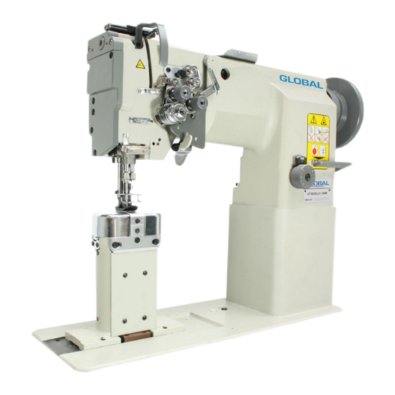
- Page 1 GLOBAL LP 9226-LH / LP 9225 LH-L & LP 9225 LH-R 2 needle/ 1 needle postbed compound feed lockstitch industrial sewing machine & Instruction Parts manual www.globalsew.com info@globalsew.com...
-
Page 3: Table Of Contents
--- CONTENTS --- Instruction Manual • Preparation for operation ............. . 1, Safety precautions ... - Page 4 C ARM SHAFT MECHANISM ............13 D, UPPER SHAFT & PRESSER FOOT MECHANISM ......... 15 E, TAKE-UP THREAD At'\/D SHAFT MECHANISM .......... 18 F, STITCH REGULATOR MECHANISM ........... 21 G, LOWER SHAFT & FEED ROCK SHAFT MECHANISM ........23 H, HOOK SADDLE MECHANISM ............26 I, OIL LUBRICATION MECHANISM .............
-
Page 5: Preparation For Operation
■ Preparation for operation: 1. Safety precautions: 1) When turning the power on, keep yoiir hands and fingers away f om the area around/under the needle and the area around the pulley. 2) Power must be turned off when the machine is nol in use, or when the operator leaves the seat. 3) Power must be turned off when lilting the machine head, installing or removing the "V"... -
Page 6: 4, Cautions On Operation
While operating the machine, check the condition of oil lubrication through the oil check window. . � :}�§ 4. Cautions on o p eration 1) When the power is turned on or off, keep foot away from the pedal. 2) It should be noted that the brake might not work when the power is intemipted or power failure occurs during sewing machine operation. - Page 7 insufficiently, t i ghten the adjusting screw. Winding tension ·, adjusting screw T11rc;1d guid j ;�::���t' � �! fully capac1ly Winding amot1nt adjusting screw Fig.5 Fig.6 3. Selection of Thread ( Fig.6) : It is reconunended to use "S" twist thread in the left needle (Viewed f om front), and "Z"...
-
Page 8: 5, Adjustment Of Stitch Length And Reverse Sewing
5. AdJustment of stitch length and reverse sewing (Fig.9): 1) Rotate the stitch length adjusting dial to change the stitch length 2) Pressing the stitch length acljusting lever for reverse stitching. 6. Setting bobbin ( Fig.10 ) : Uial �Feed reve1·se Jc,·er ---- Fig.9... -
Page 9: 11, A � Justment Of Pressure Of Presser Foot
1) The upper thread can be adjusted based on the lower thread tension. 2) Adjustment can be done by rotating the thread tension nut. 11. Adjustment of pressure of presser foot (Fig.16): 1) Pressure should be adjusted according to the material to be sewn. -
Page 10: Walking Foot And Presser Foot Vertical Stroke Adjustment
--------------·---·----------------------- 4) After adjusted, tighten the screw. The feed dog height is factory-adjusted to 1.2mm 14. Walking foot and presser foot vertical stroke adjustment (Fig.19): When fabric with large elasticity is sewn, or when thickness of fabric changes, the vertical stroke (movable range) of the presser Special bolt Crank feet should be adjusted as follows:... -
Page 11: 16, Installation Of Belt Cover
16. Installation of Belt cover (Fig.22 ): Set the screws ( 4, 6 ) and the washer ( 7 ) on the arm as illustrated. Assemble the belt guard 3 in the direction of the an-ow, tighten its screw. The assembling of the belt guard 5 is the same as the belt guard 3, then, insert the belt guard I from the top of the pulley into the inside or the 3 and 5, tighten the screws ( 2) . - Page 12 A. ARM BED AND TTS ACCESSOI� I ES (2 ) (15) 17 16 15 14 13 12...
-
Page 13: A.arm Bed And Its Accessories
A.ARM BED AND ITS ACCESSORIES ..J <n °' Fig. °' °' Part No. Description Remarks >--l ..J ..J HA30082090 Rubber plug HA30082170 Screw 11/64 (40) x9 i\03 1 471 o0800 I Oil guide pl:1te H4717D8001 Tlu·ead take-up cuvcr 1 - 1471588001 Rubber plug H47l 888001 Am1 side cover (lei\) -
Page 14: 8, Thread Tension Regulator Mechanism
B.THREAD TENSION REGULATOR MECHANISM 16 17 1 2 3 · - - - --19 � - - - - - � � �- � � ----------- 2 0 - - - - ---- - - - -21 ��- � 48 47 46 45 44 43 42 41 40 39 38 37 36 - 10 -... - Page 15 B.THREAD TENSION REGULATOR MECHANISM � •n •n °' Fig. °' °' Part No. Description Remarks Cl., Cl., ..J 0..l H2504C6510 Screw 9/64 (40) x3 H322183142 Tension releasing plate H322186812 Tension releasing spring H4705C8001 Screw H4706C8001 Lever HA731 IC306 Screw 9/64 (40) x7 H4707C8001 Mow1ting plate...
- Page 17 C.ARM SHAFT MECHANISM 11 12 13 14 ..30 29 28 27 26 (10) -13-...
-
Page 18: C Arm Shaft Mechanism
Link Link C.ARM SHAFT MECHANISM ..J •n •n °' Fig. 0- 1 °' °' Part No. Description Remarks >-l ..l ..l HA307C0662 Set screw (40) I- 1 4706D8001 Crank HAI05D0662 Set screv,, (40) HAIOOC2060 Screw 9/3 2 ( 28 ) x I 3 HA100C2070 Screw 9/32 (28) xJ4... - Page 19 D. UPPER SHAFT & PRESSER FOOT MECHANISM ( 2 ) 9 10 11 12 13 14 1 2 3 47 48 49 � · 5� 44--o- 3 � 42� 53 52...
-
Page 20: D.upper Shaft & Presser Foot Mechanism
D.UPPER SHAFT & PRESSER FOOT MECHANISM � II') °' II') Fig. °' ('.) °' Part No. Description Remarks 0... 0... 0... ,__) ..J ..J H4705E8001 Feed lifiing rock shaH H4707E8001 Bushing H003055060 (M6x0.75) H4706E8001 Set screw 1/4 (24)x7 H4709E8001 Crank 1 - 131 15F067 l Screw 1/4 (28) xJ6... - Page 21 D.UPPER SHAFT & PRESSER FOOT MECHANISM � ..] •n •n °' Fig. °' °' Part No. Description Remarks 0... 0.., .__J 0.., .__J H4718E8001 Screw l 1/64(32)x6 H2004J0662 Screw l/4(40)x5 H4719E8001 Link HAI00E2150 Screw 11/64 ( 40) H4722E8001 Washer H4721E8001 Bell crank guide H4753E8001 Screw...
- Page 22 E. TAKE-UP THREAD AND ARM SHAFT MECHANISM 28� � ldj 44 45 46 �p•' -18-...
- Page 23 E.TAKE-UP THREAD AND ARM SHAFT MECHANISM � ...J •n °' Fig. °' °' Part No. Description Remarks Cl-..J Cl..J H2421 IDN05 Oil wick H4706F8001 Needle bar guide bracket stud J- 1 4707F8001 Screw 5/16 (28) X 1().4 HAI00C2020 Set screw I 5/64 ( 28 ) x I 0 H24211DN05...
- Page 25 F.STITCH REGULATOR MECHANISM 9 10 11 12 �r (17)� �16 "'i , t � 17 ------ �� (17) 25 24 23 22 -21-...
-
Page 26: F, Stitch Regulator Mechanism
F.STITCH REGULA TOR MECHANISM ..J °' Fig. °' °' Part No. Description Remarks Cl.., 0..0..,_.J .--l .--l H6309F8001 Feed regulator HAI 13F0684 Screw I 5/64 ( 28) x8.5 H3200F2020 Screw 15/64 ( 28) H6304F8001 Link HAI00G2070 Eccentric shall H0204G8001 Reverse stitch shall H3200F2110 Spring... - Page 27 G. LOWER SHAFT & FEED ROCK SH/\FT MECHANISM 3 4 5 9 10 11 12 13 14 15 17 18 16 21 22 23 24 25 ( 16 ) 20 28 29 · ( 39 ) ( 37 ) ( 36 ) 39 ( 18 ) 35 ( 18 ) 42 41...
-
Page 28: G.lower Shaft & Feed Rock Shaft Mechanism
G.LOWER SHAFT & FEED ROCK SHAFT MECHANISM c::: ..l •n •n °' Fig. °' Part No. Description Remarks ..J ..l ..l H6315B8001 Lower shaft bushing(len) H32132B204 Oil wick H0204H8001 Lower shaft H3205H0655 Feed lifting cam H3205H0654 Set screw l/4(40)x5 H6317B8001 Lower shaft bushing(right) H32132B204 Oil wick... - Page 29 G.LOWER SHAFT & FEED ROCK SHAFT MECHANISM '° � ..J •n °' Fig. °' °' Part No. Description Remarks 0..0.., 0..H3200O2030 Holder H3200H2040 Bolt H2013J0065 Wa�her H3205H0651 Feed bar connecting fork H3205H0652 Felt H3205H0653 Screw 1/8 (44) x4 - 25 -...
- Page 30 I-I.HOOK SA DDLE MEGIAN - - - 6 fi � � � -r � i -::!- li=- t -==- = = = = = : = • � r rJ :t==1- =--- � ;;Etl =± --+ -tl- -1-- - - - _ -- 26 -...
-
Page 31: H, Hook Saddle Mechanism
H. HOOK SADDLE MECHANISM - 27 -... - Page 32 - 28 - ff.HOOK SADDLE MECHANISM � ..J •n •n °' Fig. °' °' Part No. Description Remarks 0... 0... 0..l ..l HE504J8001 Hook saddle HD804I7101 Hook HD806I8001 Bobbin HE51 IJ8001 Felt HE512J8001 Opener HE513J8001 Crank HE022K8001 Screw 11/64 02) x9 HE514J8001 Felt HE5!5J8001...
- Page 33 0... ff.HOOK SADDLE MECHANISM ..J •n °' Fig. Part No. Description Remarks n... n..J ..J ..J HE408I8001 Support plate HE412I8001 Feed bar �et bracket HE028E8001 Screw 7/32 (32) x7 HE407I8001 Cover plate HE410I8001 Felt HE409I8001 Feed dog HF504I8001 Feed dog HE411I8001 Needle plate HE406I8001...
- Page 34 - 30 - I.OIL LUBRICATION MECHANISM 9 10 11 42 43 (15) (15) ( 1) 35 34 (13) (1) (15) 33 32 (15) 31 30 29 28 27 26 25 24 23 22 21 20...
-
Page 35: I.oil Lubrication Mechanism
I.OIL LUBRICATION MECHANISM � °' Fig. °' °' Part No. Description Remarks ..J ..J ..J H/\300C2030 Screw 11/64 (40) x8 H473 lJ8001 Holder H321758304 Felt H4705J7!01 Oil pipe & wick complete H3204K00l l Oil tank complete H411040160 Screw 1 - 1 47071800 I Holder H0204K8001 Oil pipe... - Page 36 I.OIL LUBRICATION MECHANISM 0::: ..l •n •n °' Fig. °' °' Part No. Description Remarks No ..i ..:l ..:l HAI00E2150 Screw 11/64 ( 40) x I 0 l-13200K0250 Holding plate -- 32 -...
- Page 37 ].ACCESSORIES 31------p - - - -r 30 - - - - - - - - - r.,,. , .,,. (" I - -...
- Page 38 J.ACCESSORIES...
-
Page 39: J.accessories
J.ACCESSORIES � ..l •n °' Fig. °' °' Part No. Description Remarks � H4740F8001 Needle HE037J8001 Bobbin HA300J2230 Washer H801045200 Wood screw H3200L0020 Vibration preventing rnhber H3200L0030 Vibration preventing 111bbcr HA307J0067 Hinge complete HA!00J2!20 Magnet HA300J2070 Screw driver (larger) H3214L0067 Small parts JI I H3214L2011...
Need help?
Do you have a question about the LP 9226-LH and is the answer not in the manual?
Questions and answers