
Related Manuals for Global LP 9916


Summary of Contents for Global LP 9916
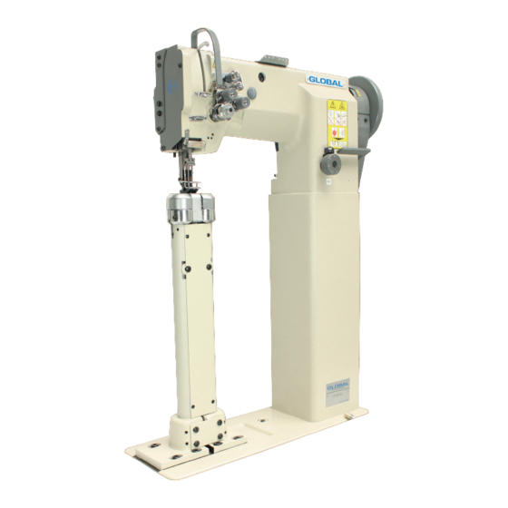
- Page 1 GLOBAL LP 9916 High Postbed, 2 needle walking foot sewing machine Instruction & Parts manual www.globalsew.com info@globalsew.com...
-
Page 3: Table Of Contents
--- CONTENTS --- Instruction Manual • ............. . Preparation for operation 1, Safety precautions .............. -
Page 5: Preparation For Operation
■ Preparation for operation: 1. Safety prec�utions: 1 ) When turning the power on, keep y our hands and fingers away from the area around/under the needle and the area around the pulley. Power must be turned off when the machine is not in use, or when the operator leaves the seat. 3) Power must be turned off when tilting the machine head, installing or removing the "V"... -
Page 6: Cautions On Use
■ Cautions on use 1. Oiling (1) (Fig.l) Filling the oil reservoir with oil up to "H" mark. Oil level should be periodically checked. If oil; level is found below "L"; level replenish oil to "H" level. Use white spindle oil. 2. -
Page 7: Winding Of Bobbin Thread
2. Winding of bobbin thread (Fig.5) Note: When bobbin thread is wound, keep the presser foot lifted. Adjustment: Tension of wound thread: Slack winding is recommended for polyester thread and nylon thread. Conically wound thread Move the thread guide toward smaller diameter of wound thread layer. Length of wound thread Loosen the thread length adjusting screw to increase length of thread and tighten the screw to decrease length of thread. -
Page 8: Needle Thread Tension
Needle thread tension should be adjusted in reference to bobbin thread tension. 7. Needle thread tension (Fig.11) To adju�t needle thread tension, turn each tension adjusting nut. Needle thread tension can be also adjusted for special fabric and thread by changing intensity and movable range of slack thread adjusting spring. -
Page 9: 11, Relationship Between Rotating Hook Motion And Take- Up Lever Motion
1 ) Lean the machine head backward. 2) Turn the hand wheel by hand and stop when the feed dog rises to the maxinrum height. Loosen the feed setscrew. Vertically move the feed bar (in the direction indicated by arrow in the figure) to adjust it to - a dequate height. -
Page 10: Safety Clutch Device
13. Safety clutch device (Fig.20.21) Safety clutch device is installed to prevent the hook and cog belt from damage in case the thread is caught into the hook when the machine is loaded abnormally during operation. 1) Function of safety clutch A. -
Page 11: Adjustment
1 ) Loosen the special bolt. 2) The vertical strokes of the presser feet become maximum when the crank rod is moved upward and set. The vertical strokes become minimum when the nut is moved downward and set. After the adjustment, fully tighten the special bolt. The vertical strokes of the presser feet can be adjusted within·... -
Page 12: A.arm Bed And Its Accessories
A.ARM BED AND ITS ACCESSORIES 1 2 (2) 1 5 1 4 (12) (2)-----'... - Page 13 P,m :\o �o. Rubber plug I-L<\300B2090 11/64 ( 40) X9 Screw HA300B2l 70 H4716B8001 Oil guide plate Thread take-up cover H4717B8001 Rubber plug H4715B8001 Aln1 side cover (left) H4718B8001 H2000B2010 Rubber plug Alm side cover (right) H4719B8001 }1/64 (40) X8 Screw HA700B2060 H2400B2I00...
-
Page 15: B, Thread Tension Regulator Mechanism
B.THREAD TENSION REGULATO R MECHA NISM Fig. Part No. Name Description H322IB68l l Screw SM9/64 (40) ><3 H3221B3142 Tension releasing plate I--B22IB6812 Tension releasing spring • • � . . . H4705C8001 Screw SM9/64 ( 40) x4.2 _· H4706C8001 Le�er B06 HA 7311 C306 Screw SM9/64 ( 40) x4.5 H4707C8001 Mounting plate... - Page 16 ------ 20 C .A RM SH A FT .M E C HA N I SM b : � � i.,..,,< � '\'"" !V\. ..,__ .-. , --.L 28 27 26 12 -...
- Page 17 C.ARM SHAFT MECHANISM � ..i Fig. Part No. Description Remarks HA307C0662 Set screw 1/4 (40) x6 H4706D8001 Crank HA105D0662 Set screw 1/4 (40) x4 HAIOOC2060 Screw 9/3 2 ( 28 ) HA100C2070 Screw 9/32 (28) xJ4 H4708D8001 Set screw l/4(24)x 13 Felt H32111Bl04 Arm shaH bushing (Jell)
- Page 18 PRE SSE R FOO T MEC HAN ISM D.UP PE R SHA FT & 9 10 11 12 13 14 (2) 5 1 2 3 5 0 5 � 5� 4 4 -0- � 42 � 20 19 - 1 4 -...
- Page 19 D.UPPER SHAFT & PRESSER FOOT MECHANISM -15- 0::: ...l Fig .. Part No. Description Remarks H4705E8001 Feed lifting rock shaft H4707E8001 Bushing H003055060 (M6x0.75) H4706E8001 Set screw 1/4 (24)x7 H4709E8001 Crank H3 J 15F0671 Screw 1/4 (28) XJ6 H2013J0065 Washer H2014J0066 Connecting rod H2000J2100 Screw...
- Page 20 D.UPPER SHAFT & PRESSER FOOT MECHANISM � ...l Fig. Part No. Description Remarks H4718E8001 Screw 11/64(32)x6 H2004J0662 Screw 1/4(40)x5 H4719E8001 Link HAI0OE2150 Screw 11/64 (40) xIO H4722E8001 Washer H4721E8001 Bell crank guide H4753E8001 Screw 11/64 (40) Xl7.5 H4708D8001 Set screw l/4(24)X}3 HE204I8001 Finger gusrd...
- Page 21 � 2 7 � � E. TAKE-UP THREAD AND ARM SHAFT MECHANISM 10 11 12 13 - 17 -...
- Page 22 E.TAKE-UP THREAD AND ARM SHAFT MECHANISM H24211DN05 Oil wick H4706F8001 Needle bar guide bracket stud Screw H4707F8001 5/16 (28) xl0.4 Set screw HA100C2020 15/64 (28) xJQ H24211DN05 Oil wick H24211DM05 Thread take-up lever support stud H4712F8001 Thread take-up lever H2405Dl 112 Thread take-up slide brock HA110D0672 Screw...
- Page 23 F.STITCH REGULATOR MECHA\ I S\I )w� �12 t-- - - (16)� 37�� 28 27 33 3...
- Page 25 H4706G8001 Feed regulator HAI 13F0684 Screw 15 6➔ H3200F2020 Screw 1516➔ ; ::8 H7104G8001 Link HAIOOG2070 Eccentric shaft H4709G8001 Reverse stitch shaft H3207F0671 Reverse stitch crank HA800F2020 Screw 15/64 ( 28) x}3.5 HA100F2110 Washer HAI 13F0684 Screw 15/64 (28) x8.5 Fl 1 H4711G8001 Feed reversing lever...
- Page 26 G.LOWER SHAFT & FEED ROCK SHAFT MECHANISM 11 12 13 14 15 18 19 20 21 � - 22 -...
- Page 27 H4706H8001 Lower shatl bushing(lefl) H4707H8001 Oil wick H7107H8001 Lower shall H4710H8001 Feed lifting cam H3205H0654 Set screw 1/4(40)x5 H4712H8001 Lower shall bushing(right) H4713H8001 Oil wick H007013050 Stop ring GB/f896 H4714H8001 Spring H4715H8001 Push button H2405D0664 Screw 15/64(28)X l4 G l2 H4717H8001 Feed eccentric H47!8H8001...
- Page 28 H3205G0662 Oil wick H7106H8001 Feed bar H429050050 Screw H3200H2040 Screw 15/64(28)X2Q.5 H20!3J0065 Washer H3205H0653 Screw J/8(44)x4 H3205H0652 Felt H4743H8001 Feed bar forked connection G.LOWER SHAFT & FEED ROCK SHAFT MECHANISI\: I Fig. Part No. Description Remarks - 24 -...
- Page 29 H.FEED BAR MECHANISM )�· - 25 -...
- Page 30 H.FEED BAR MECHANISM � ,-..l Fig. Part No. Description Remarks Screw H710818001 H710418001 Feed bar - H0 4 H710518001 Square block - H0 5 H7!06I8001 Screw H711318001 Screw H0 7 8320800675 - 26 -...
- Page 31 MECHANISM I. HOOK SADDLE 'i � l_t 6 . j'- a � "' � ✓ 16 � � - 27 -...
- Page 32 - 28 - I.HOOK SADDLE MECHANISM i:x:: Fig. Part No. Description Remarks H7124J8001 Screw H7123J8001 Sl ide plate - H7109J8001 Hook saddle - H5337D8001 Screw 9/64(36)x30 H2400I2020 Bobbin .. H7127J7101 Hook H7125J8001 Opener - ms· H41622D216 Square block H410270D16 H7115J8001 Cover plate - Screw HA105D0662...
- Page 33 J.OIL LUBRICATION MECHANISM 36 37 26 27 (12)24 23 22 21 20 19 18 17 16 15 30 31 - 29 -...
- Page 34 - 30 - i:i::: H4731J8001 Holder H4705J7101 Oil pipe & wick complete H3204K0011 Oil tank complete H411040160 Screw GBff819.1 M4xl6 H4707J8001 Holder H7109K8001 Oil pipe H7110K8001 Oil pipe H7111K7101 Oil pipe complete HA7311CC06 Screw 9/64( 40)x 6. 5 I- i 2000Mo110 Holder H4714J8001 Holder...
- Page 35 K. ACCESSORIES ( I ) 22 21 17 16 15 14 13 34 - - - - - - - - - - - --r - - - - - - � �10 ..- 31 -...
- Page 36 K. ACCESSORIES ( I ) (38) (38) (38) - 32 -...
- Page 37 84705K8001 Needle DPx17 23# 8240012020 Bobbin HA300J2230 Washer 8801045200 Wood screw GB/T99 4.5X20 83200L0020 Vibration preventing rubber 83200L0030 Vibration preventing rubber 8802060250 Screw GB/TIO0 6x25 82404K0654 8inge(l) 82404K0655 8inge(2) Screw H2404K0656 HA100J2120 Magnet HA300J2070 Screw driver (larger) H7122L8001 Crank HAJ06J0664 Screw 15/64(!8)x)3 Knee lifler pin...
- Page 39 LP-9916 SPECIAL PARTS 6 -------' --'----' ·� Needle plate 9916H7109 Needle clamp screw 120037 Needleplate screw 10. 123117 Needle holder screw 120245 11. 9916H545 Needle plate Needle bar assm. 9916H4806 12. H3200E2020 Outer presserfoot screw 9916H7107 Feeddog 13. 9916H7105 Outer presserfoot Feeddog screw H7108I8001 14.
Need help?
Do you have a question about the LP 9916 and is the answer not in the manual?
Questions and answers