Advertisement
Quick Links
Advertisement

Related Manuals for Global LP 9915-L


Summary of Contents for Global LP 9915-L
- Page 1 GLOBAL LP 9915-L / -R Instruction & parts Manual www .globalsew .corn info@globalsew .corn...
- Page 3 1. Safety precautions 2. Precaution before Starting Operation 3. Precaution for Operating Conditions PRE. C URTIONS BEFORE STARTING OPERATION 1) When. turning the power on. keep your hands and fing1:rs a<,,vay from the an�a around/under the needle and the area around the pu!:ey. Power must be turned off .vhen the machine is not useri.
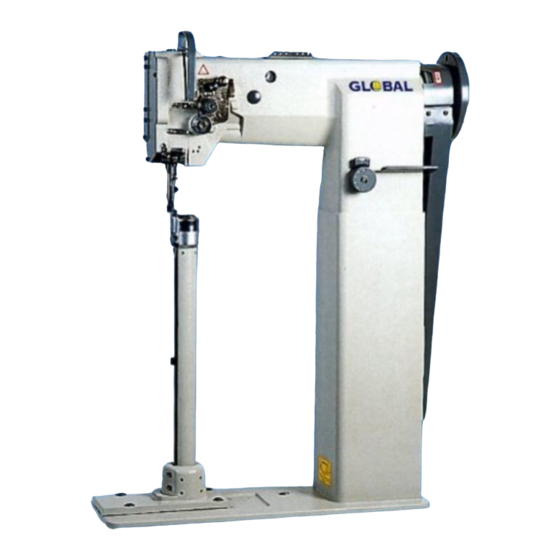
- Page 6 Motor PREPARATION FOR OPERATION Overall view of assembled Balance wheel sewing machine Pow er push but tun -- 1 --...
- Page 7 CAUTIONS ON USE Oiling Filling the oil reseNoir with oil up to "H" mark. Oi level Oil level should be periodically checked. If oil mark levei is found below "L" level replenish oil to "H" level. For oil, Use white spindle oil Oiling (2) £.
- Page 8 3. Oiling condition See dripping of oil through the oil sight hole to check oiling condition during operation. - - = � -� � sight ------ window 4. Cautions on operation ( 1) When the power is turned on or off, keep foot away from the pedal. (2) It should be noted that the brake might not work when the power is interrupted or power failure occurs during sewing machine operation.
- Page 10 2. Winding of bobbin thread Note: When bobbin thread is wound, keep the presser foot lifted. Adjustment: Tension of wound thread Slack winding is recommended for polyester thread and nylon thread. Conically wound thread Move the thread guide toward smaller diameter of wound thread layer. Length of wound thread Loosen the thread length adjusting screw to increase length of thread and tighten the screw to decrease length of t�:read.
- Page 11 3. Selection of thread It is recommended to use "S" twist thread in the Left needle (viewed from front), and "Z' twist thread in the right needle. When discriminate use of needle threads is impossible, use "Z" twist thread in both the needles. For bobbin thread, "S"...
- Page 13 7. Needle thread tension • Needle thread tension should be adjusted in reference to bobbin thread tension. • To adjust needle thread tension, turn each tension adjusting nut. Needle thread tension can be also adjusted for special fabric and thread by changing intensity and movable range of slack thread adjusting spring.
- Page 15 10.Adjustment of feed dog height Height of feed dog and pressure of presser Foot should be adjusted for individual fabric(s) With the following cautions: • Fabric will be damaged if the feed dog extends too high, or pressure of presser foot is too large.
- Page 16 11. Relationship between rotating hook motion and take-up lever motion when the timing belt (toothed belt) was removed for i � s replacement, for example, the relationship between rotating hook motion and take-up lever motion should be adjusted as follows: (1) Turn the balance wheel and stop when the take-up lever is lifted to its upper dead point.
- Page 18 13.SAFETY CLUTCH DEVICE: clutch Safety / ,✓, : :.· /�- Safety clutch device is installed to prevent the hook � - . � Cog bell pulley and cog belt from damage in case the thread is og belt hub caught into the hook when the machine is loaded abnormally during operation.
- Page 20 15.0utside presser foot and inside presser vertical stroke adjustment When fabric with large elasticity is sewn, Or When thickness of fabric changes, the vertical Stroke (movable range) of the Special bolt press feet should be adjusted as follows: Adjustment : · • , r t- .
- Page 21 Model LP9915R LP9915L Specitication Right Position of post-bed Left Heavy m�terial Application 1600rpn1 Max.sewing speed Stitch length 0-- 6 1nIY1 74.51nn1 Thread take-up lever stroke 36mm 1'✓eedle-bar stroke 8 by hand 5 h';; · Pr€sser-foot strGke 1- .__v ~ 2-6mm Vertical stroke of upper feed Needle No.
- Page 23 A:BODY AND IT'S\CCESSORIES Description Pcs. Ref.No. H71A001 Rubber plug H71A002 Screw H71A003 Oil guard piate H71A004 Thread take-up cover H71A005 Rubber plug H71A006 Side cover(left) H71A007 Rubber plug H71A008 Side cover(right) H71A009 Strew H71A010 Thread guide H71A011 Rubber plug H71A012 Screw H71A013 Cover...
- Page 24 � � ► tT:1 � -�-- - - - - •• ·•" � � ;,,,., ---21 � :-,9)�, � � � � 3 5 }A,. 3� 37...
- Page 25 Pcs. Ref.No. Description 111 I UV I ,J B:THREAD TENSION REGULATOR MECHANISM H71B001 Screw H71B002 Tension releasing plate H71B003 Tension releasing spring H71B004 Screw H71B005 Lever H71B006 Screw H71B007 Mounting plate H71B008 Stop ring H71B009 Mounting plate H71B010 Screw H71B011 Spring H71B012 Push button...
- Page 26 B:THREAD TENSION REGULATOR MECHANISM Pcs. Ref.No. Description H71B037 H71B038 Screw H71B039 Stopper...
- Page 28 C:UPPER SHAFT MECHANISM Pcs. Ref.No. Description H71C001 Needle bar crank complete H71C002 Screw H71C003 Screw H71C004 Screw H71C005 Screw H71C006 Arm shaft bushing(left) H71C007 Screw H71C008 Felt H71C009 Arm shaft H71C010 Spring flange H71C011 Screw H71C012 Belt pulley(upper) H71C013 Screw H71C014 Bearing H71C015...
- Page 29 ·I 9 8 10 11 12 1314 Cl'J C/.J. t_Tj '"!J , _ , � >-:,I � 2 � 9 ► � 20 � _.--:::9 r� � 15 / 45 32 3 9 3 �� ____-o- .. . :·•··••• • · . . ,..,,.1.0s••- •·�«.. _ ..
- Page 30 D:PRESSER FOOT MECHANISM Pcs. Ref.No. Description H710001 Feed lifting rock shaft H710002 Screw H710003 Bushing H710004 H710005 Lever H710006 Screw H710007 Washer H710008 Bolt H710009 Connecting rod H710010 Oil pipe $ wick complete H710011 Spring H710012 C-type stop ring H710013 Eccentric H710014 Screw...
- Page 31 Pcs. Ref.No. Description � D:PRESSER FOOT MECHANISM H71D037 Snap pin H71D038 Collar H71D039 Screw H71D040 Screw H71 D041 Bushing H71D042 Spring bracket H71D043 Screw � H71D044 Lifter lever H71D045 Screw H71D046 Bracket H710047 Screw H71D048 Presser bar H71D049 Screw i· f"...
- Page 32 E:NEEDLE BAR AND THREAD TAKE-UP LEVER MECHANISM...
- Page 33 Pcs. Ref.No. Description E:NEEDLE BAR AND THREAD TAKE .. UP LEVER MECHANIS H71 E001 Oil wick H71E002 Needle bar guide bracket stud H71E003 Screw H71 E004 Screw H71E005 Oil wick H71E006 Thread take-up lever support stud H71E007 Thread take-up lever ,·...
- Page 34 Pcs. Ref.No. Description E:NEEDLE BAR AND THREAD TAKE .. UP LEVER MECHANIS H71E037 Bushing H71E038 Screw H7i E039 Needle bar vibrating crank(right) H71E040 H71E041 Link H71 E042 Screw H71E043 Oil wick ', . H71E044 Square block...
- Page 35 F: STITCI-I REGlJLATOR MECHANISJ\1 9 10 38 37 36 32 3 1 30 29 20 19...
- Page 36 F:STITCH REGULATOR MECHANISM Pcs. Ref .No. Description Feed regulator cam H71 F001 Screw H71 F002 Screw H71 F003 Link H71F004 Eccentric shaft H71 F005 Reverse stitch shaft(upper) H71F006 Crank H71 FOO? � Screw H71 FOOS Washer H71 F009 Screw 2· H71F010 Lever H71 F011...
- Page 38 \til ��� � - � - • r ..., _. __. - - ·"· · �· -, : ; � �; • • f ,.._ � � ,...__.._.._.--- ;:-/" .., ,-._ ..,, ,.__, -• ..-r.,,-',-- � � �...
- Page 39 G:LOW SHAFT AND FEED R.OCKING MOTION MECHANISM Pcs. Ref.No. Description r...--,,.,4 H71 GOOi Lower shaft bushing(left:) H71G002 Oil wick H71G003 Lower shaft H71 G004 Feed eccentric cam H71G005 Screw H71G006 Lower shaft bushing(right) H71G007 Oil wick H71G008 Stop ring H71G009 Spring H71G010 Push button...
- Page 41 H: FEED BAR MECHANISM...
- Page 42 H:FEED BAR MECHANISr\11 - - · Pcs. No . Description Ref .No. Feed dog H71 HOO1 Screw H71HOO2 Feed bar H71HOO3 Square block H/1HOO4 Screw H71HOO5 Screw H71HOO6 H71 HOO? Cover H71 HOOS Screw H71 HOO9 - - - �-...
- Page 44 l:HOOK SADDLE MECHANISM Description Pcs. Ref.No. Screw H71I001 Hook cover H71I002 Hook saddle H71I003 Screw H71I004 Bobbin H71I005 Hook complete H71I006 Opener H71I007 Slide block H71I008 H71I009 Plate H71I010 Screw H71I011 Screw H71I012 Collar H71I013 Hook shaft H71I014 Screw H71I015 Spring H71I016 Screw...
- Page 45 / � � � ► � � � 3 6 ' ► � 2 0 ' 19 2 3 22 21 (1 3) 2 5 24 2 7 2 6 2 11...
- Page 46 J:OIL LUBRICATION MECHANISM Pcs. Description Ref.No. Felt H71J001 Oil pipe complete H71J002 Oil reservoir complete H71J003 Screw H71J004 Holder H71J005 Oil pipe §ix *80 H71J006 Oil pipe §�x�80 H71J007 Oil pipe complete H71J008 Screw H71J009 Spring washer H71J010 Holder H71J011 Holder H71J012 Screw...
- Page 47 J:OIL LUBRICATION rVIECHANISM Pcs. Description Ref.No. H71J037 Holder H71J038 Screw ---- 'c.· •·...
- Page 48 K:ACCESSORIES � ----- 30 � 2Q � - - --< <:>...
- Page 49 Ref .No. Description Pcs. K:ACCESSORIES .• .•. · .• H71K001 Thread a needle kit ➔ H71K002 Screw driver(small) H71K003 Screw driver(middle) H71K004 needle OPx 1-22 H71K005 Socket wrench H71K006 3obbin H71K007 Washer H71K008 Screw H71K009 Vibration oreventing ��it.ber H71K010 Vibration preventing ri _ ;bber H71K011 Oiler H71K012...
- Page 50 @ &J [FJ@� - --+- -- - --- ---- -- Ron van Hoevelaak operations manager Global Parts bv Hendrik Figeeweg 4b NL - 2031 BJ Haarlem The Netherlands Tel. +31 (0)23 542 53 12 Fax +31 (0)23 542 34 22 E-mail globalparts@planet.nl...
Need help?
Do you have a question about the LP 9915-L and is the answer not in the manual?
Questions and answers