Panasonic HL-C211F Instruction Manual
Ultra high-speed, high-accuracy laser displacement sensor
Hide thumbs
Also See for HL-C211F:
- User manual (278 pages) ,
- Instruction manual (2 pages) ,
- Instruction manual (2 pages)
Advertisement
Quick Links
INSTRUCTION MANUAL
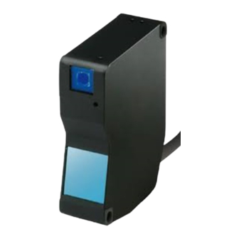
Ultra High-Speed, High-Accuracy Laser Displacement Sensor
Sensor Head
HL-C211F(E), HL-C211F(E)-MK
MJE-HLC211F No.0097-63V
Thank you very much for purchasing Panasonic products. Read this Instruction Man-
ual carefully and thoroughly for the correct and optimum use of this product. Kindly
keep this manual in a convenient place for quick reference.
WARNING
This product is intended to detect the objects and does not have the control func-
tion to ensure safety such as accident prevention.
Do not use the product as a sensing device to protect human body.
The product was developed and manufactured for industrial use.
BEFORE USE
Before using the product, check the sensor head model and contents of packing.
Sensor head model
Check the model name of product at the top of sensor head.
Packing
Check that all of the following components are included in the
package.
• 1 sensor head unit
• 1 Instruction manual
• Laser warning labels
[JIS/IEC/KS: 1 set, GB: 1 set (E type only), FDA: 1 set]
This product complies with CE Marking when used together with a controller and
programmable display unit that are in compliance with CE Marking. Likewise, the
product complies with UKCA Marking when used together with a controller and
programmable display unit that are in compliance with UKCA Marking.
1
DESCRIPTION
HL-C211F(E), HL-C211F(E)-MK displacement sensor head achieves ultra high-
speed and high-accurate measurement using linear image sensor as light receiv-
ing element to be used on equipment that require high-speed operation with high-
accuracy.
2
CAUTIONS ON HANDLING LASER LIGHT
In order to prevent the accidents by laser product and protect the users, IEC, JIS,
GB, KS and FDA establish the following standards respectively.
IEC : IEC 60825-1
-2014
JIS : JIS C 6802
-2014
GB : GB 7247.1
-2012
KS : KS C IEC 60825-1
-2013
FDA : PART 1040.10, 1040.11
vide the safety measures for respective classes (Refer to the "FDA Standard" table).
FDA standard
Class
*1
Requirements
I
IIa
II
IIIa
Performance (all laser products)
*2
*2
*2
*2
Protective housing [1040.10 (f) (1)]
R
R
R
R
*3,4
*3,4
*3,4
*3,4
Safety interlock [1040.10 (f) (2)]
R
R
R
R
R
Location of controls [1040.10 (f) (7)]
N/A
R
R
R
Viewing optics [1040.10 (f) (8)]
R
R
R
R
Scanning safeguard [1040.10 (f) (9)]
R
R
R
R
Performance (laser system)
Remote control connector [1040.10 (f) (3)]
N/A
N/A
N/A
N/A
Key control [1040.10 (f) (4)]
N/A
N/A
N/A
N/A
Emission indicator [1040.10 (f) (5)]
N/A
N/A
R
R
R
Beam attenuator [1040.10 (f) (6)]
N/A
N/A
R
R
Reset [1040.10 (f) (10)]
N/A
N/A
N/A
N/A
Medical [1040.11 (a)]
S
S
S
S
*8
Measurement, leveling, alignment [1040.11 (b)]
S
S
S
S
Demonstration [1040.11 (c)]
S
S
S
S
Labeling (all laser products)
R
R
R
R
Protective housing [1040.10 (g) (6),(7)]
D
*5
R
*5
R
*5
R
*5
Aperture [1040.10 (g) (4)]
N/A
N/A
N/A
N/A
*6
*7
*9
Class warning [1040.10 (g) (1),(2),(3)]
N/A
R
R
R
R
Information (all laser products)
User information [1040.10 (h) (1)]
R
R
R
R
Product literature [1040.10 (h) (2) (i)]
N/A
R
R
R
Service information [1040.10 (h) (2) (ii)]
R
R
R
R
R : Required
N/A : Not applicable
S : Same as for other products of that Class. Also see footnotes.
NP : Not permitted
D : Depends on level of inner radiation
*1 : Class is based on the maximum level of laser exposure during operation.
*2 : Required wherever and whenever human access to laser radiation above Class I limits is not
needed for product to perform its functions.
*3 : Required for protective housings opened during operation or maintenance, if human access
thus gained is not always necessary when housing is opened.
protective housing.
*6 : Warning statement label
*7 : CAUTION logotype
*8 : The method to measure the level of laser radiation to human body is required.
-2
-2
*9 : CAUTION if 2.5mWcm
or less, DANGER is greater than 2.5mWcm
.
*12 : DANGER logotype
*13 : Required after August 20, 1986.
Warning / Aperture label
WARNING label
In Japanese / English / Korean
In Chinese
<Label position>
Install the product so the laser beam comes higher or lower than eye level in or-
der not to watch the beam directly during operation.
Please contact our company if the system breaks down. It is not equipped with a func-
tion that stops laser radiation automatically during disassembling the sensor head.
The users therefore may be exposed to laser beam in disassembling the sensor head.
3
EXPORT REGULATIONS BY JAPANESE GOVERNMENT
HL-C211F and HL-C211F-MK are subject to export control regulation by the For-
eign Exchange and Foreign Trade Law. Export admission by Japanese govern-
ment is required before the product is to be exported or brought out of the country.
These products are also subject to Article 1.B.3.b.1 of Nuclear Suppliers Group in
international export control regime and 2.B.6.b.1 of Wassenaar Arrangement.
Please follow the export control regulations required.
HL-C211FE and HL-C211FE-MK (E type) are not subject to export control regula-
tions under the condition that they are used combined with the non-pertinent con-
When they are combined with the pertinent controller to export control, they are
subject to the Law. In this case export admission by Japanese government is re-
quired before the product is to be exported or brought out of the country.
-
4
SPECIFICATIONS
HL-C211F(E)
IIIb
IV
Model No.
Meas. method (Note 2)
*2
*2
R
R
Measurement center distance
110mm
106.7mm
*3,4
*3,4
R
Measurement range (Note 3)
±15mm
±14.5mm
R
R
R
R
Red semiconductor laser Class II (FDA), Class 2 (JIS/IEC/GB/KS)
Beam source
Max output: 1mW, Emission Peak wavelength: 658nm
R
R
Beam diameter (Note 4)
R
R
Beam receiving element
Linear image sensor
R
R
Resolution
*10
*10
R
R
R
Linearity
N/A
R
*13
Temperature characteristics
0.01%F.S./°C
Laser emission
Green LED: Lights up during laser emission.
S
*8
S
*8
NP
NP
Meas. range
Yellow LED: Near measurement center:ON, within measurement range:Blink, beyond the range:OFF
S
*11
S
*11
Protective structure
IP67 (except connector)
Pollution degree
R
R
Insulation resistance
20M ohms or more by 500V DC megger (between all the terminals and enclosure.)
R
*5
R
*5
Commercial Frequency
AC 500V for 1min. (between all the terminals and enclosure.)
N/A
N/A
*12
*12
R
Impulse
±
R
R
Vibration resistance
R
R
X, Y, and Z directions for 2 hours
R
R
Shock resistance
196m/ s
2
in X, Y, and Z directions for 3 times
Ambient illuminance (Note 6)
Ambient temperature
0 to +45°C (No dew condensation or icing allowed), At storage: -20 to +70°C
Ambient humidity
35 to 85%RH At storage: 35 to 85%RH
Ambient Height
2,000m or less
Material
Main unit case / cover: Die-cast aluminum, Front cover: Glass
Cable length
Cable extension
Extendible to 30m long maximum using the optional extension cable.
Weight
Approx. 300g including cable weight
Applicable regulations
Compliant with EU Law: EMC Directive / British Legislation: EMC Regulation
tance, object substance: white ceramic,, and digital measurement value.
2)
3)
not subject to "Foreign Exchange and Foreign Trade Law".
6) The variation in ambient illuminance is ±0.03%F.S. or less.
5
CAUTIONS
Connection
When connecting or disconnecting the connectors, be sure to hold the connector
area not to apply extra force to the cable.
Be careful not to touch terminals or to let foreign matter get in the connector after
disconnecting connectors.
Be careful not to apply force to around the connector of standard cable and ex-
tension cable. Do not bend the cables near connectors. Failure to do so causes
causes disconnection of the cable.
Wiring
Do not run the sensor cable along (bundled in parallel) with other wirings. Keep it
(E type only)
at least 100mm away from other wires. Run the cable so it is separate from high
voltage and power circuit lines. If it is necessary to run the cable in parallel with
them, shield it by running through a grounded electrical conduit.
Install the product as far away as possible from noise source such as high-voltage
lines, high-voltage device, power lines, power device, machines which generate a
large starting and stopping surge, welding machines and inverter motor.
Do not pull the cable using a force more than
29.4N when routing the cable with the sensor
head and controller fixed. At least 20 mm is
required from the cable connection to the bend.
The bending radius must be 30 mm or more.
When the sensor head is moved around while
in use, the cable in the moving part may be
damaged. Therefore, use an extension cable for
the moving part and, when the extension cable
is damaged, immediately replace it. Otherwise, it
may result in failure.
Cable Extension
Use only one extension cable for connection
between one sensor head and a controller.
When the sensor head part is moved around
while in use, fix the extension cable at a
position 100 mm away from the mobile end.
Warming up time
Allow at least 30 minutes of warming up after turning on the power to ensure the
performance of the product.
Environment
The life of the semiconductor laser depends on the ambient temperature during
use. When using the product near a heat source, take measures to lower the am-
bient temperature of the sensor head as possible. Mount the sensor on a device
having good heat radiation because the sensor itself emits heat.
Notes: 1) When installing 2 sensor heads in parallel at a 20mm or less interval, mount each sensor head on an alumi-
num or iron plate having a 200cm
ing paper.
Install the sensor head so ambient light such as sunlight or light with the same
wavelength as laser beam should not enter the light receiver. If high accuracy is
required, install a light shielding plate or the like on the sensor head.
The controller and connectors are not structurally dustproof, waterproof, or corro-
HL-C211F(E)-MK
sion-resistant. Do not use the product underwater or in the rain.
gases, droplet, direct sunlight, severe vibration or impact.
110mm
106.7mm
±15mm
±14.5mm
Setting
ues when the sensor head is connected to the controller of Version 1.1* or earlier.
Measurement Value A +15.000000[mm], Correction Value a +15.000[V]
Measurement Value B -15.000000[mm], Correction Value b -15.000[V]
±0.03%F.S.
Value a and -5.000[V] for Correction Value b when the sensor head is connected
to the controller of Version 1.2* or later.
2
6
MEASUREMENT RANGE / INDICATOR
Meas. range indicator
0.5m
-
the center of limited measurement range.
2
(approximately 13.5%)
7
MUTUAL INTERFERENCE AREA (Unit: mm)
When installing 2 or more sensor heads side
by side, mutual interference occurs if the laser
spots from other sensor heads fall within the
heads so the laser spots from other sensor
heads fall outside the shaded areas.
8
BEAM DIAMETER (Unit: mm)
20mm or more
HL-C211F(E)
Minimal spot type
Bending end
HL-C211F(E)-MK
Line spot type
Fixing position
Mobile end
9
DIMENSIONS (Unit: mm)
100mm or more
2
surface area.
-
Installation Mode: Specular
-
10
OPTION
received light intensity to an optimum level. This is useful when mounting the sen-
OFF
Blink
ON
Blink
OFF
Measurement range
Measurement center
distance
Panasonic Industry Co., Ltd.
1006, Oaza Kadoma, Kadoma-shi, Osaka 571-8506, Japan
https://industry.panasonic.com/
Please visit our website for inquiries and about our sales network.
Panasonic Industry Co., Ltd. 2024
April, 2024
0.24
0.08
0.24
0.2
0.08
0.2
Measurement range
Measurement center distance
1.2
1.7
2.2
0.2
0.08
0.2
2-M5 mounting hole
Depth:10
(Measurement center distance)
(opposite surface)
Laser emission indicator
(green)
Light emission axis
Measurement
Light
range indicator
reception axis
(yellow)
Beam Attenuator
(Measurement center distance)
Light emission axis
Light reception axis
Beam Attenuator
HL-C2F01) is optionally available to adjust the excessive
PRINTED IN JAPAN
Advertisement

Related Manuals for Panasonic HL-C211F


Summary of Contents for Panasonic HL-C211F
- Page 1 Light emission axis ing element to be used on equipment that require high-speed operation with high- accuracy. Measurement HL-C211F and HL-C211F-MK are subject to export control regulation by the For- Light range indicator Environment reception axis (yellow) eign Exchange and Foreign Trade Law.
- Page 2 35 85 RH 35 85 RH 2,000m 0.5m 300g 24V DC 20°C 40 s 20 s 15.0mm 14.5mm CAUTION 10 s 12.5 15.0mm 12.5 14.5mm 13.5% 2.5mWcm CAUTION 2.5mWcm DANGER “ ” 0.25 m 0.03 F.S. Panasonic Industry Co., Ltd. 2024 DANGER...
Need help?
Do you have a question about the HL-C211F and is the answer not in the manual?
Questions and answers