Advertisement
Quick Links
FTPLCG-0144
FTPLCG-0380
FTPLCG-0145
FTPLCG-0381
FTPLCG-0146
FTPLCG-0382
FTPLCG-0147
FTPLCG-0383
FTPLCG-0148
FTPLCG-0384
1. Must use ground nails, ropes, and expansions screws for
whichever ground you install on for stability to avoid devastat-
ing injuries for people inside or nearby and property damage
caused by a collapsing gazebo.
2. Do not use this gazebo in high winds, heavy snow, or inclem-
ent weather. It is not designed to withstand strong gusts of wind,
heavy snow accumulation, or other inclement weather. Must
take precautions when the wind speed exceeds 25Mph, and
clear snow when it accumulates more than 2 inches.
3. Before use, thoroughly inspect the gazebo to make sure all
bolts, nuts, and buckles have been completely tightened and
securely fastened.
4. Warranty does not cover damages, losses, or injuries resulting
from improper installation, misuse, not using stability accesso-
ries mentioned above, non snow cleaning, failure to take pre-
cautionary measures, etc.
FTPLCG-0385
FTPLCG-0386
FTPLCG-0387
FTPLCG-0388
FTPLCG-0389
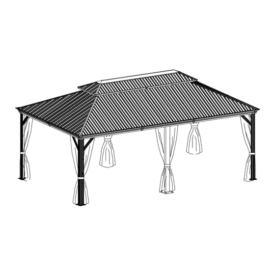
12X20 FT
LHHY-V 3
Advertisement

Subscribe to Our Youtube Channel
Related Manuals for YitaHome FTPLCG-0144


Summary of Contents for YitaHome FTPLCG-0144
- Page 1 FTPLCG-0144 FTPLCG-0380 FTPLCG-0385 FTPLCG-0145 FTPLCG-0381 FTPLCG-0386 FTPLCG-0146 FTPLCG-0382 FTPLCG-0387 FTPLCG-0147 FTPLCG-0383 FTPLCG-0388 LHHY-V 3 FTPLCG-0148 FTPLCG-0384 FTPLCG-0389 12X20 FT 1. Must use ground nails, ropes, and expansions screws for whichever ground you install on for stability to avoid devastat- ing injuries for people inside or nearby and property damage caused by a collapsing gazebo.
- Page 2 ASSEMBLY INSTRUCTIONS "IMPORTANT, RETAIN FOR FUTURE REFERENCE: READ CAREFULLY" 1. Two or more people are required for assembly. 2. A ladder and electric drill may be necessary. 3. Do not erect the structure in heavy winds or inclement weather. 4. Do not leave up this unit for extended periods of time, as it is not a permanent structure or designed to withstand sustained wind or rain.
- Page 3 ASSEMBLY INSTRUCTIONS Item no. Reference Image Qty.
- Page 4 ASSEMBLY INSTRUCTIONS Item no. Reference Image Qty. X152 X160...
- Page 5 ASSEMBLY INSTRUCTIONS Item no. Reference Image Qty. Item no. Reference Image Qty.
- Page 6 ASSEMBLY INSTRUCTIONS Item no. Reference Image Qty. X4+X2 X4+X2...
- Page 7 ASSEMBLY INSTRUCTIONS Qty. Qty. Item no. Reference Image Item no. Reference Image X330 M6X15mm X100 M6X23mm M6X25mm ST4.8X12mm M6X42mm M6X47mm M6X15mm M6X10mm...
- Page 8 ASSEMBLY INSTRUCTIONS 4pcs 4pcs 12pcs...
- Page 9 ASSEMBLY INSTRUCTIONS 2pcs 2pcs 2pcs 8pcs When connecting B and B1 via P, make sure that 3 holes on part P (as shown in the picture) should be facing upwards. Do not install it upside down.
- Page 10 ASSEMBLY INSTRUCTIONS 2pcs 2pcs 20pcs...
- Page 11 ASSEMBLY INSTRUCTIONS 2pcs 2pcs 24pcs...
- Page 12 ASSEMBLY INSTRUCTIONS 2pcs 2pcs 2pcs 4pcs 16pcs When connecting B1 and B2 via P, B2 and B via P, make sure that 3 holes on part P (as shown in the picture) should be facing upwards. Do not install it upside down.
- Page 13 ASSEMBLY INSTRUCTIONS 2pcs 2pcs 2pcs 2pcs 36pcs...
- Page 14 ASSEMBLY INSTRUCTIONS 2pcs 2pcs 2pcs 2pcs 44pcs...
- Page 15 ASSEMBLY INSTRUCTIONS 16pcs 16pcs...
- Page 16 ASSEMBLY INSTRUCTIONS 4pcs 4pcs 32pcs...
- Page 17 ASSEMBLY INSTRUCTIONS 4pcs 16pcs...
- Page 18 ASSEMBLY INSTRUCTIONS 152pcs When sliding 8 x hook U onto each rail of parts B &B1&B2, they should face inward. The same for sliding 7 x hook U on rails of parts B and B1. X7 X7 X7 X7...
- Page 19 ASSEMBLY INSTRUCTIONS 6pcs 6pcs 6pcs 12pcs...
- Page 20 ASSEMBLY INSTRUCTIONS 2pcs 2pcs 8pcs...
- Page 21 ASSEMBLY INSTRUCTIONS 12pcs...
- Page 22 ASSEMBLY INSTRUCTIONS 4pcs 4pcs 8pcs 12pcs 4pcs 4pcs...
- Page 23 ASSEMBLY INSTRUCTIONS 4pcs...
- Page 24 ASSEMBLY INSTRUCTIONS 2pcs 4pcs 2pcs 24pcs...
- Page 25 ASSEMBLY INSTRUCTIONS 3pcs 2pcs...
- Page 26 ASSEMBLY INSTRUCTIONS 2pcs 2pcs 2pcs 4pcs 12pcs...
- Page 27 ASSEMBLY INSTRUCTIONS 2pcs 2pcs 2pcs 2pcs 2pcs 2pcs 2pcs 2pcs 36pcs 8pcs 2pcs 2pcs Z Z1 Attach Z and Z1 by lightly tapping with a screwdriver.
- Page 28 ASSEMBLY INSTRUCTIONS 2pcs 2pcs 2pcs 2pcs 2pcs 2pcs 2pcs 2pcs 2pcs 2pcs 36pcs 8pcs 2pcs 2pcs 2pcs 2pcs 8pcs 2pcs 2pcs Attach Z and Z1 by lightly tapping with a screwdriver.
- Page 29 ASSEMBLY INSTRUCTIONS...
- Page 30 ASSEMBLY INSTRUCTIONS 2pcs 2pcs 2pcs 4pcs 2pcs 12pcs...
- Page 31 ASSEMBLY INSTRUCTIONS 4pcs 4pcs 4pcs 4pcs 8pcs 36pcs...
- Page 32 ASSEMBLY INSTRUCTIONS 2pcs 2pcs 2pcs 2pcs 2pcs 16pcs...
- Page 33 ASSEMBLY INSTRUCTIONS...
- Page 34 ASSEMBLY INSTRUCTIONS...
- Page 35 ASSEMBLY INSTRUCTIONS...
- Page 36 ASSEMBLY INSTRUCTIONS 160pcs 100pcs 4pcs 8pcs 48pcs Notes: 1. When installing the ceiling , fix the screws on the central beam first to prevent the iron sheet from falling and causing injury. 2. Do not fully secure the screw until all screws are properly in position.
- Page 37 ASSEMBLY INSTRUCTIONS 4+2pcs The other part has 8 holes One part of the hanging on curtain has 7 holes Part B. hanging on Part B1. The other part has8holes hanging on Part B2. One part of the curtain has 7 holes The other part hanging on Part B.
- Page 38 ASSEMBLY INSTRUCTIONS Pay attention to the sidewall curtain's installation position.
- Page 39 ASSEMBLY INSTRUCTIONS 4+2pcs The other part has 8 holes One part of the hanging on netting has 7 holes Part B. hanging on Part B1. The other part has 8 holes hanging on Part B2. One part of the netting has 7 holes The other part hanging on Part B.
- Page 40 ASSEMBLY INSTRUCTIONS Note: Attach 1 to 2 to secure parts T1 and T (curtains) together. Attach 1 to 3 to secure the back curtain (T). Attach 1 to 3 to secure the front curtain (T1). Pay attention to the sidewall Hang the hook attached to netting's installation position.
- Page 41 ASSEMBLY INSTRUCTIONS 18pcs 18pcs To improve wind resistance, be sure to complete this installation step. If expansion screws or ground nails are not installed,strong winds Cement surfaces may topple the gazebo. Expansion screws are essential for stability on cement surfaces, and ground nails are for grassy surfaces.
Need help?
Do you have a question about the FTPLCG-0144 and is the answer not in the manual?
Questions and answers