Advertisement
Quick Links
Advertisement

Related Manuals for YitaHome FTPLCG-0193


Summary of Contents for YitaHome FTPLCG-0193
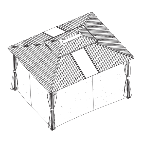
- Page 1 ASSEMBLY INSTRUCTIONS NBQF-V1 FTPLCG-0193 FTPLCG-0194 FTPLCG-0195 10X12 FT HARDTOP GAZEBO...
- Page 4 ASSEMBLY INSTRUCTIONS Item no. Reference Image Qty. Item no. Reference Image Qty. I...
- Page 5 ASSEMBLY INSTRUCTIONS Item no. Reference Image Qty. Item no. Reference Image Qty. M6X10mm X149 M6X15mm M6X25mm M6X30mm ST5X10mm ST5X16mm M6X50mm M6X30mm...
- Page 12 ASSEMBLY INSTRUCTIONS 8pcs...
- Page 15 ASSEMBLY INSTRUCTIONS 4pcs 4pcs...
- Page 24 ASSEMBLY INSTRUCTIONS...
- Page 27 ASSEMBLY INSTRUCTIONS 2pcs 2pcs...
- Page 28 ASSEMBLY INSTRUCTIONS 4pcs 4pcs 2pcs 4pcs 8pcs Part H and H1 should be placed as shown in the picture. The side views are marked by triangles. Part M3 should be inserted between part H and H1.
- Page 31 ASSEMBLY INSTRUCTIONS 32pcs 28pcs 2pcs 4pcs...
- Page 32 ASSEMBLY INSTRUCTIONS 32pcs 28pcs 4pcs 4pcs 4pcs...
- Page 35 ASSEMBLY INSTRUCTIONS 2pcs 2pcs 2pcs 2pcs 4pcs I I I Do not tighten the screw X1 and X7 before completing step 30. It’s view from the bottom inside gazebo.
- Page 36 ASSEMBLY INSTRUCTIONS 2pcs 2pcs 2pcs 2pcs Tighten the screw after completing Z2. It’s view from the bottom inside gazebo.
- Page 37 ASSEMBLY INSTRUCTIONS 2pcs 8pcs It’s view from the bottom inside gazebo.
Need help?
Do you have a question about the FTPLCG-0193 and is the answer not in the manual?
Questions and answers