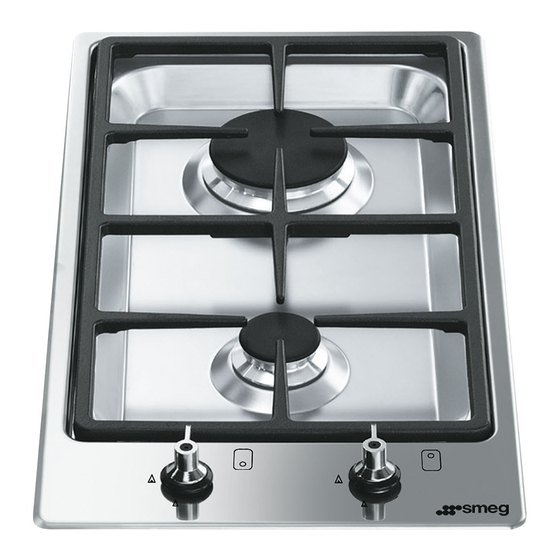
Smeg PGA32G Manual
Hide thumbs Also See for PGA32G:

Advertisement

1. INSTRUCTIONS FOR USE ................................................................ 4
2. SAFETY PRECAUTIONS ................................................................... 6
3. ENVIRONMENTAL RESPONSIBILITY ............................................... 8
4. USING THE HOB................................................................................ 9
5. CLEANING AND MAINTENANCE.................................................... 12
6. POSITION NEAR THE COUNTER TOP .......................................... 15
7. ADAPTATION TO DIFFERENT TYPES OF GAS ............................ 24
8. FINAL OPERATIONS ....................................................................... 26
THESE INSTRUCTIONS ARE VALID ONLY FOR THE DESTINATION COUNTRIES
WHOSE IDENTIFYING SYMBOLS ARE INCLUDED ON THE COVER OF THIS MAN-
UAL.
INSTRUCTIONS FOR THE USER: these instructions contain user
recommendations, a description of the controls and the correct
procedures for cleaning and maintenance of the appliance.
INSTRUCTIONS FOR THE INSTALLER: these are intended for the
authorized person who must install the appliance, set it functioning and
carry out an inspection test.
Contents
3

Advertisement

Table of Contents
loading

Summary of Contents for Smeg PGA32G

  • Page 1: Table Of Contents

    7. ADAPTATION TO DIFFERENT TYPES OF GAS ......24 8. FINAL OPERATIONS ............... 26 THESE INSTRUCTIONS ARE VALID ONLY FOR THE DESTINATION COUNTRIES WHOSE IDENTIFYING SYMBOLS ARE INCLUDED ON THE COVER OF THIS MAN- UAL. INSTRUCTIONS FOR THE USER: these instructions contain user recommendations, a description of the controls and the correct procedures for cleaning and maintenance of the appliance.
  • Page 2: Instructions For Use

    THE MANUFACTURER CANNOT BE HELD RESPONSIBLE FOR USES OTHER THAN THOSE INDICATED. IF THE APPLIANCE IS INSTALLED ON BOATS OR IN CARAVANS, DO NOT USE IT AS A ROOM HEATER. UNSUITABLE IN MARINE CRAFT, CARAVANS OR MOBILE HOMES, UNLESS EACH BURNER IS FITTED WITH A FLAME SAFEGUARD NEVER USE THIS APPLIANCE TO HEAT YOUR ENVIRONMENT.
  • Page 3: General Instructions

    DO NOT USE OR STORE FLAMMABLE MATERIALS IN THE APPLIANCE STORAGE DRAWER OR NEAR THIS APPLIANCE. THIS APPLIANCE IS DESIGNED FOR COOKING FOOD AND IT SHALL NOT BE USED AS A SPACE HEATER. IN CASE OF SERVICE, CONTACT YOUR NEAREST SERVICE AGENT DISTRIBUTOR...
  • Page 4: Safety Precautions

    DO NOT REMOVE THIS PLATE ON THE CASING FOR ANY REASON. BEFORE CONNECTING THE DEVICE, MAKE SURE THAT IT HAS BEEN REGULATED FOR THE TYPE OF GAS THAT WILL FEED IT, CHECKING THE LABEL UNDER THE CASING. BEFORE CARRYING OUT INSTALLATION/MAINTENANCE WORK, MAKE SURE THAT THE APPLIANCE IS NOT CONNECTED TO THE POWER GRID.
  • Page 5 General instructions DO NOT LET CHILDREN GO NEAR THE APPLIANCE WHEN IT IS IN OPERATION OR PLAY WITH IT AT ANY TIME. DO NOT INSERT POINTED METAL OBJECTS (CUTLERY OR UTENSILS) INTO THE SLITS IN THE APPLIANCE. DO NOT USE STEAM JETS FOR CLEANING THE APPLIANCE.
  • Page 6: Environmental Responsibility

    You can obtain the addresses of collection, recycling and disposal centres from your retailer or from the competent local organisations. Do not discard the packaging or any part of it, or leave it unattended. It can constitute a suffocation hazard for children, especially the plastic bags.
  • Page 7: Using The Hob

    If the burners should go out accidentally, after about 20 seconds a safety device will be tripped, cutting off the gas supply, even if the gas tap is open. Turn off the control knob and wait at least 1 minute before trying to re-light the burner.
  • Page 8 2 Semi rapid 16 - 22 5 Ultra-rapid 20 - 26 The following are the diameters of the pans that can be used with the raised pan stand: HOB BURNER Ø min. and max. (in cm) 1 Auxiliary 16 - 26...
  • Page 9 2 Semi rapid 16 - 24 5 Ultra-rapid 20 - 26 The following are the diameters of the pans that can be used with the raised pan stand: HOB BURNER Ø min. and max. (in cm) 1 Auxiliary 16 - 26...
  • Page 10: Cleaning And Maintenance

    To clean and preserve the stainless steel surfaces, use only specific products that do not contain abrasives or chlorine-based acids. How to use: pour the product onto a damp cloth and wipe the surface, rinse thoroughly and dry with a soft cloth or chamois leather.
  • Page 11 Instructions for the user In models with central pan stand, fit this piece, taking care that its centre is perfectly aligned with the centre of the burner In models equipped with pan stands, fit as shown in the figure, taking care to position them exactly as shown.
  • Page 12 Valves: if the gas valves get stuck or hard to turn, they need to be cleaned and re-greased; this operation must be carried out by an authorised person.
  • Page 13: Position Near The Counter Top

    Carefully position the supplied insulating seal on the outer edge of the hole on the top hob, as indicated in figure 2. Try and make it stick to the whole surface by applying light hand pressure. The front and back sides of the seal must be touching the hole.
  • Page 14 Instructions for the installer PGA64 PSA906 PGA75SC3 PGA95SC3 (only “906” models) PGA32...
  • Page 15 Make sure that there is a minimum of 750 mm between the hob ring flames and any shelves placed directly above them (Fig. 1). Furthermore, this kind of appliance needs a milling on the hob top of 3 mm in depth;...
  • Page 16 PGA75F3 - PGA75FSC3 PGA95F3 - PGA95FSC3 (only “906” models) If laminated surfaces are used, it is advisable to spread a layer of anti-infiltration “primer” across the milled surface. Important: Other types of installation are possible if supervised by the manufacturer!
  • Page 17 Obstructions: location of gas and electric connectors (measured in mm). PGA64F PGA75F3 - PGA75FSC3 PSFA906 PGA95F3 - PGA95FSC3 PGA32 Precautions: the temperature of the inside surface of the hob may exceed 125°C. To avoid any hazardous situations, over-the-hob access must be restricted. Refer to the installation instructions.
  • Page 18 IMPORTANT: if the appliance is mounted on a unit, make sure that a separating shelf is installed, as shown in the figure. However, if the appliance is on an oven installed under the hob, there is no need to install a separating shelf.
  • Page 19: Clearances Above And Around Domestic Appliances

    Range hoods and exhaust fans shall be installed in accordance with the manufacturer’s instructions. However, in no case shall the clearance between the highest part of the hob of the cooking appliance and a range hood be less than 600 mm or, for an overhead exhaust fan, 750 mm.
  • Page 20 Do not remove this plate for any reason. The plug at the end of the supply cable and the wall socket must be of the same type and must conform to the applicable legislation on electrical installations.
  • Page 21 Ensure appliance is secured to wall when installation is completed. N.G. The regulator supplied must be fitted to the ½ BSP thread at the rear of the appliance. An approved manual shut-off valve must be installed. The N.G.
  • Page 22 If it is not possible to make the openings in the room where the cooker is installed, the necessary air may be taken from an adjoining room, proveded it is not a bedroom or a room with fire risk.
  • Page 23: Adaptation To Different Types Of Gas

    Before carrying out the following operations, disconnect the appliance from the power supply. The appliance is preset for natural gas NG at a pressure of 1.0 kPa. In the case of operation with other types of gas, the burner nozzles must be changed and the minimum flame adjusted on the gas taps.
  • Page 24 Instructions for the installer Burner and nozzle characteristics table Burner ULPG – 2.75 kPa Nominal gas Injector Consumption (MJ/h) (mm) Auxiliary (1) 0.54 Semi rapid (2) 0.68 Reduced rapid (3) 0.85 Rapid (4) 10.8 0.88 Ultra rapid (5) 15.0 1.05 Centre 0.50...
  • Page 25 Instructions for the installer Arrangement of the burners on the cooking hob HOB BURNER 1 Auxiliary 2 Semi rapid 3 Reduced Rapid 4 Rapid 5 Ultra-rapid 6 Dual control...
  • Page 26: Final Operations

    "7.1 Replacement of the cooking hob nozzles". After adjustment with a gas other than the preset one, replace the label on the casing of the appliance with the label corresponding to the new gas. This label can be obtained from the nearest Authorised Service Centre.

This manual is also suitable for:

Pga64Pga75-4Pga75f-4Pga95-4Pga95f-4Psa906

Table of Contents