Advertisement
Quick Links
IMPORTANT! Read all instructions before installing and using. Installer: This manual must be
delivered to the end user.
!
WARNING!
Failure to install or use this product according to manufacturer's recommendations may result in property
damage, serious bodily/personal injury, and/or death to you and those you are seeking to protect!
Do not install and/or operate this safety product unless you have read and understand the
safety information contained in this manual.
1. Proper installation combined with operator training in the use, care, and maintenance of emergency warning devices are
essential to ensure the safety of you and those you are seeking to protect.
2. Exercise caution when working with live electrical connections.
3. This product must be properly grounded. Inadequate grounding and/or shorting of electrical connections can cause high
current arcing, which can cause personal injury and/or severe vehicle damage, including fire.
4. Proper placement and installation are vital to the performance of this warning device. Install this product so that output
performance of the system is maximized and the controls are placed within convenient reach of the operator so that s/he
can operate the system without losing eye contact with the roadway.
5. It is the responsibility of the vehicle operator to ensure during use that all features of this product work correctly. In use, the
vehicle operator should ensure the projection of the warning signal is not blocked by vehicle components (i.e., open trunks
or compartment doors), people, vehicles, or other obstructions.
6. The use of this or any other warning device does not ensure all drivers can or will observe or react to a warning signal.
Never take the right-of-way for granted. It is your responsibility to be sure you can proceed safely before entering an
intersection, driving against traffic, responding at a high rate of speed, or walking on or around traffic lanes.
7. This equipment is intended for use by authorized personnel only. The user is responsible for understanding and obeying
all laws regarding warning signal devices. Therefore, the user should check all applicable city, state, and federal laws and
regulations. The manufacturer assumes no liability for any loss resulting from the use of this warning device.
Specifications:
Size:
Weight:
Input Voltage:
Installation & Mounting:
Carefully remove the unit from its packaging. Examine the
unit for transit damage. If damage is found, return the product
to your local dealer for warranty replacement. Do not use
damaged or broken parts.
The ED3779 series directionals should be mounted to a flat
surface or one with the least amount of curvature. The mounting
location should allow the maximum visibility of the warning device
to other road users, while allowing for sufficient wire access.
Caution:
When drilling into any vehicle surface, make
sure the area is free from any electrical wires, fuel lines,
vehicle upholstery, etc. that could be damaged.
Installation and Operation Instructions
5.1" W x 3.4" H x 1.3" D
0.62 lbs.
12-24 VDC
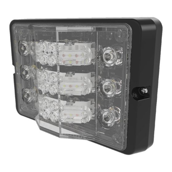
ED3779 Series Directionals
Current Draw at 12.8 VDC:
Flash Rate:
Temperature Range:
Surface Mounting:
1. Mark drill hole locations on the mounting surface using the
directional and bezel as a template.
2. Drill mounting holes using a 3.74 mm drill bit. Drill a 10 mm
hole for routing the wires as needed.
3. Mount the directional with the bezel and gasket, routing the
wires through the 10 mm hole using additional grommets or
cable protection as necessary to protect the wiring from any
sharp edges. Secure the directional to the surface using the
supplied thread forming screws.
1.7 A Max.
See flash pattern charts.
-22°F to 122°F
Page 1 of 6
Advertisement

Related Manuals for Ecco ED3779 Series


Summary of Contents for Ecco ED3779 Series
- Page 1 2. Drill mounting holes using a 3.74 mm drill bit. Drill a 10 mm The ED3779 series directionals should be mounted to a flat hole for routing the wires as needed. surface or one with the least amount of curvature. The mounting 3.
-
Page 2: L-Bracket Mounting
4. Mount the directional and bracket to the mounting surface, The ED3779 Series of directional LED light heads are self routing the wires through the 10 mm hole using additional flashing. All wiring should be a minimum of 20 AWG. The... - Page 3 Page 3 of 6...
- Page 4 Page 4 of 6...
- Page 5 Page 5 of 6...
-
Page 6: Customer Service
833 West Diamond St Boise, Idaho 83705 Customer Service USA 800-635-5900 UK +44 (0)113 237 5340 AUS +61 (0)3 63322444 www.eccoesg.com An ECCO SAFETY GROUP™ Brand www.eccosafetygroup.com Page 6 of 6 920-0722-00 Rev. A...
Need help?
Do you have a question about the ED3779 Series and is the answer not in the manual?
Questions and answers