Table of Contents
Advertisement
Quick Links
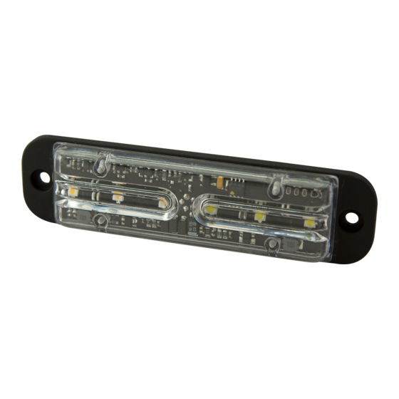
ED3701 and ED3702 directional LEDs are bright and versatile warning lights that
are suited to a wide variety of applications. Their utra-low profile makes them easy
to install virtually anywhere on a vehicle. Both models offer wide angle optics and
multiple flash patterns, including synchronization with other units for simultaneous
or alternating operation. ED3701 models feature 6 LEDs and are available in either
single color or split-color (3 LEDs of each color). The ED3702 is a dual-color light
featuring 12 LEDs (6 of each color) and available in 7 color configurations. This
manual provides information about installation, function, safety , maintenance,
replacement parts and warranty.
!
WARNING!
Failure to install or use this product according to manufacturers recommendations may result in property damage, serious injury, and/or death to
those you are seeking to protect!
Do not install and/or operate this safety product unless you have read and understand the safety information
contained
1.
Proper installation combined with operator training in the use, care, and maintenance of emergency warning devices are essential to ensure
the safety of you and those you are seeking to protect.
2.
Exercise caution when working with live electrical connections.
3.
This product must be properly grounded. Inadequate grounding and/or shorting of electrical connections can cause high current arcing,
which can cause personal injury and/or severe vehicle damage, including fire.
4.
Proper placement and installation are vital to the performance of this warning device. Install this product so that output performance of the
system is maximized and the controls are placed within convenient reach of the operator so that s/he can operate the system without losing
eye contact with the roadway.
5.
Do not install this product or route any wires in the deployment area of an air bag. Equipment mounted or located in an air bag deployment
area may reduce the effectiveness of the air bag or become a projectile that could cause serious personal injury or death. Refer to the
vehicle owner's manual for the air bag deployment area. It is the responsibility of the user/operator to determine a suitable mounting location
ensuring the safety of all passengers inside the vehicle particularly avoiding areas of potential head impact.
6.
It is the responsibility of the vehicle operator to ensure during use that all features of this product work correctly. In use, the vehicle operator
should ensure the projection of the warning signal is not blocked by vehicle components (i.e., open trunks or compartment doors), people,
vehicles or other obstructions.
7.
The use of this or any other warning device does not ensure all drivers can or will observe or react to a warning signal. Never take the right-
of-way for granted. It is your responsibility to be sure you can proceed safely before entering an intersection, driving against traffic, respond-
ing at a high rate of speed, or walking on or around traffic lanes.
8.
This equipment is intended for use by authorized personnel only. The user is responsible for understanding and obeying all laws regarding
warning signal devices. Therefore, the user should check all applicable city, state, and federal laws and regulations. The manufacturer as-
sumes no liability for any loss resulting from the use of this warning device.
CONTENTS:
1
Light Head
1
Gasket:
Includes-
2- M4x25 Sheet metal screws
Wire: ED3701
RED: Positive(need to add 2A Fuse)
BLACK: Negative
BLUE: Pattern Switch
YELLOW: Synchronized Function
(Up to 8 units can be Synchronized)
Wire: ED3702
RED: Positive, Colors 1 & 3 (need to add 5A Fuse)
WHITE: Positive, Colors 2 & 4 (need to add 5A Fuse)
BLACK: Negative
BLUE: Pattern Select to negative
YELLOW: Synchronized Function
(Up to 8 units can be Synchronized)
Operation Environment:
Ambient Temperature: -30 to 50°C
920-3701-00 Rev. E
Installation and Operation Instructions
Directional LED
SPECIFICATIONS:
Input Voltage
Work Current
Important! This unit is a safety device and it must be connected to its own separate, fused
power point to assure its continued operation should any other electrical accessory fail.
Caution: When drilling into any vehicle surface, make sure the area is free from any electrical
wires, fuel lines, vehicle upholstery, etc. that could be damaged
Phase Opertion:
Phase 1 (Ph1) flashes simultaneously with Ph1
Phase 2 (Ph2) flashes simultaneously with Ph2
Ph1 alternates with Ph2
(Up to 8 units can be Synchronized)
Apply BLUE TO BLACK wire:
-Less than 1 sec. for next pattern
-Between 1-3 sec for previous pattern
-Between 3-5 sec. for factory default pattern
-More than 5 sec. for pattern 12 (ED3702) and pattern 13
(ED3701)
12-24VDC
ED3701 = 1.0A@12VDC
ED3702 = 1.2A@12VDC
Page 1 of 12
Advertisement
Table of Contents

Related Manuals for Ecco ED3701


Summary of Contents for Ecco ED3701
- Page 1 Both models offer wide angle optics and multiple flash patterns, including synchronization with other units for simultaneous or alternating operation. ED3701 models feature 6 LEDs and are available in either single color or split-color (3 LEDs of each color). The ED3702 is a dual-color light featuring 12 LEDs (6 of each color) and available in 7 color configurations.
- Page 2 Mounting: ED3701 Series Flash Pattern Chart Diagrama de patrones de intermitencia de la Serie ED3701 Tableau des modes de clignotement de la série ED3701 SAE J595 CA T13 ECE R65 LAMP PATTERN MODE PATTERNS AMBER BLUE WHITE AMBER BLUE AMBER...
- Page 3 ED3702 Series Flash Pattern Chart Diagrama de patrones de intermitencia de la Serie ED3702 Tableau des modes de clignotement de la série ED3702 SAE J595 CA T13 ECE R65 LED Color Color 1 & Color PAT- Color 2 & ED3702 FLASH 1 &...
- Page 4 ED3702 Series Flash Pattern Chart Diagrama de patrones de intermitencia de la Serie ED3702 Tableau des modes de clignotement de la série ED3702 SAE J595 CA T13 ECE R65 LED Color Color 1 & Color 3 PAT- color 1 & 2 &...
- Page 5 ED3702 Series Flash Pattern Chart Diagrama de patrones de intermitencia de la Serie ED3702 Tableau des modes de clignotement de la série ED3702 SAE J595 CA T13 ECE R65 LED Color Color 1 & Color 3 PAT- color 1 & 2 &...
- Page 6 Trouble Shooting The ED3701-ED3702 series has been factory tested and approved. If the functions of the device fail, please check the following: 1. After connecting with the power supply, be sure that the power source end is joined correctly. Make sure there is not a short circuit.
-
Page 7: Especificaciones
Instrucciones de instalación y operación LED direccional Los LED direccionales ED3701 y ED3702 son luces de advertencia brillantes y versátiles que se adaptan a una amplia gama de aplicaciones. Su perfil ultrabajo las hace fáciles de instalar en casi cualquier lugar del vehículo. Ambos modelos ofrecen una amplia óptica de ángulo con patrones de flash múltiples, inclusive sincronización... -
Page 8: Montaje
Localización de fallas Las series ED3701-ED3702 han sido probadas en fábrica y aprobadas. Si las funciones del dispositivo fallan, verifique lo siguiente: 1. Luego de conectar la alimentación, asegúrese de que el extremo de la fuente de energía esté bien conectado. Asegúrese de que no haya un cortocircuito. - Page 9 Limitación de responsabilidad y garantía limitada del fabricante: El fabricante garantiza que al momento de la compra, este producto cumple con las especificaciones del fabricante para el mismo (disponibles a pedido). El fabricante garantiza además que el presente producto está libre de defectos en sus materiales y en su fabricación.
-
Page 10: Instructions D'installation Et D'utilisation
Les modèles ED3701 sont équipés de 6 DEL et sont disponibles en couleur unie ou en couleur irisée (3 DEL de chaque couleur). L’ED3702 est une lampe à... -
Page 11: Dépannage
Dépannage La série ED3701-ED3702 a été testée et approuvée en usine. Si les fonctions de l’appareil sont défectueuses, veuillez vérifier les choses suivantes : 1. Après raccordement à l’alimentation électrique, assurez-vous que le raccordement est correct du côté de la source d’alimentation. - Page 12 Garantie limitée et limitation de responsabilité du fabricant : Le fabricant garantit qu’à la date d’achat ce produit sera conforme aux caractéristiques techniques définies par ses soins (disponibles sur demande) et qu’il est exempt de vices de fabrication et de main-d’œuvre. La présente garantie limitée est valable trente-six (36) mois à compter de la date d’achat.
Need help?
Do you have a question about the ED3701 and is the answer not in the manual?
Questions and answers