Advertisement
Quick Links
IMPORTANT! Read all instructions before installing and using. Installer: This manual must be delivered to the end user.
WARNING!
Failure to install or use this product according to manufacturer's recommendations may result in property damage, serious injury, and/or
death to those you are seeking to protect!
Do not install and/or operate this safety product unless you have read and understood the safety information
contained in this manual.
1.
Proper installation combined with operator training in the use, care, and maintenance of emergency warning devices are essential to
ensure the safety of emergency personnel and the public.
2.
Emergency warning devices often require high electrical voltages and/or currents. Exercise caution when working with live electrical
connections.
3.
This product must be properly grounded. Inadequate grounding and/or shorting of electrical connections can cause high current arcing,
which can cause personal injury and/or severe vehicle damage, including fire.
4.
Proper placement and installation is vital to the performance of this warning device. Install this product so that output performance of
the system is maximized and the controls are placed within convenient reach of the operator so that they can operate the system without
losing eye contact with the roadway.
5.
Do not install this product or route any wires in the deployment area of an air bag. Equipment mounted or located in an air bag
deployment area may reduce the effectiveness of the air bag or become a projectile that could cause serious personal injury or death.
Refer to the vehicle owner's manual for the air bag deployment area. It is the responsibility of the user/operator to determine a suitable
mounting location ensuring the safety of all passengers inside the vehicle particularly avoiding areas of potential head impact.
6.
It is the responsibility of the vehicle operator to ensure daily that all features of this product work correctly. In use, the vehicle operator
should ensure the projection of the warning signal is not blocked by vehicle components (i.e., open trunks or compartment doors),
people, vehicles or other obstructions.
7.
The use of this or any other warning device does not ensure all drivers can or will observe or react to an emergency warning signal.
Never take the right-of-way for granted. It is the vehicle operator's responsibility to be sure they can proceed safely before entering an
intersection, drive against traffic, respond at a high rate of speed, or walk on or around traffic lanes.
8.
This equipment is intended for use by authorized personnel only. The user is responsible for understanding and obeying all laws
regarding emergency warning devices. Therefore, the user should check all applicable city, state, and federal laws and regulations. The
manufacturer assumes no liability for any loss resulting from the use of this warning device.
Specifications:
Size:
ED3703
3.63"L x 1.38"W x 0.75"H
ED3704
4.69"L x 1.38"W x 0.75"H
ED3705
6.19"L x 1.38"W x 0.75"H
Weight:
ED3703
0.10 lbs.
ED3704
0.13 lbs.
ED3705
0.18 lbs.
Voltage Range:
12-24 VDC
Current draw at 12.8 VDC:
ED3703
0.44 A. Max.
ED3704
0.60 A. Max.
ED3705
0.86 A. Max.
Prior to Installation:
Carefully remove the unit from its packaging. If damage is found, contact the transit company or ECCO. Do not use broken or damaged parts. Prior to mounting, con-
sideration should be given to cable location.
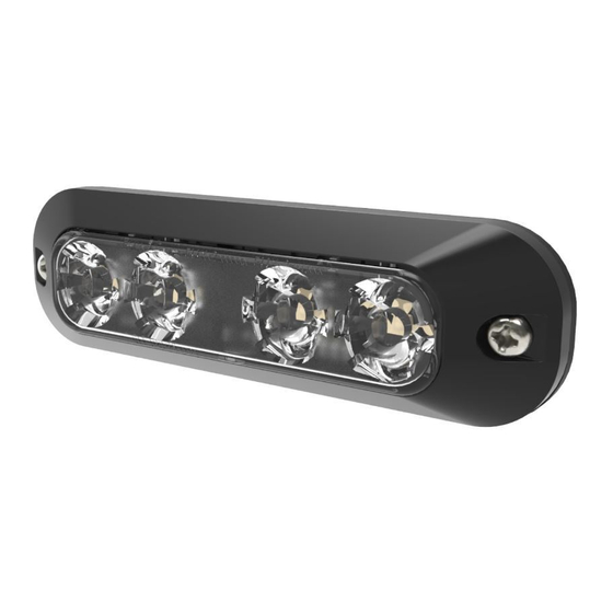
Installation and Operation Instructions
ED3703, ED3704 and ED3705 Series
LED Directionals
Power Consumption at 12.8 VDC:
ED3703
ED3704
ED3705
Temperature Range:
Flash Rate:
5.6 W. Max
7.7 W. Max
11.0 W. Max
-40° to 149°F
-40° to 65°C
See Flash Pattern Charts
Page 1 of 4
Advertisement

Related Manuals for Ecco ED3704


Summary of Contents for Ecco ED3704
- Page 1 0.86 A. Max. Prior to Installation: Carefully remove the unit from its packaging. If damage is found, contact the transit company or ECCO. Do not use broken or damaged parts. Prior to mounting, con- sideration should be given to cable location.
- Page 2 Synchronization: The directional is capable of syncing with other compatible ECCO products by following the steps below: 1. Set the desired flash pattern on each unit individually. It is also strongly recommended that the same rate and style of flash pattern be used on all synced units to produce the most effective warning pattern.
- Page 3 Double, Triple Flash - Wig Wag Single, Quad Flash - Wig Wag Steady Burn - Color 1 & 2 Replacement Parts and Accessories: Part No. Description ED3703 ED3704 ED3705 Black Bezel Kit EZD3703BLBZ EZD3704BLBZ EZD3705BLBZ Chrome Bezel Kit EZD3703CHMBZ EZD3704CHMBZ EZD3705CHMBZ...
- Page 4 Electronics Controls Company “ECCO” (Manufacturer) ECCO warrants that on the date of purchase, this product will conform to ECCO’s specifications for this product (which are available from ECCO upon request). This Limited Warranty extends for thirty-six (36) months from the date of purchase.
Need help?
Do you have a question about the ED3704 and is the answer not in the manual?
Questions and answers