Table of Contents
Advertisement
Quick Links
WARNING:
RECOGNIZE THIS SYMBOL
AS AN INDICATION OF
IMPORTANT SAFETY
INFORMATION
WARNING
THESE INSTRUCTIONS
ARE INTENDED AS AN AID
TO QUALIFIED, LICENSED
SERVICE PERSONNEL FOR
PROPER INSTALLATION,
ADJUSTMENT, AND
OPERATION OF THIS UNIT.
READ THESE INSTRUCTIONS
THOROUGHLY BEFORE
ATTEMPTING INSTALLATION
OR OPERATION. FAILURE
TO FOLLOW THESE
INSTRUCTIONS MAY
RESULT IN IMPROPER
INSTALLATION,
ADJUSTMENT, SERVICE,
OR MAINTENANCE
POSSIBLY RESULTING IN
FIRE, ELECTRICAL SHOCK,
PROPERTY DAMAGE,
PERSONAL INJURY, OR
DEATH.
Do not destroy this manual.
Please read carefully and
keep in a safe place for future
reference by a serviceman.
[ ] indicates metric conversions.
92-21354-105-00 ( / ) Printed in USA
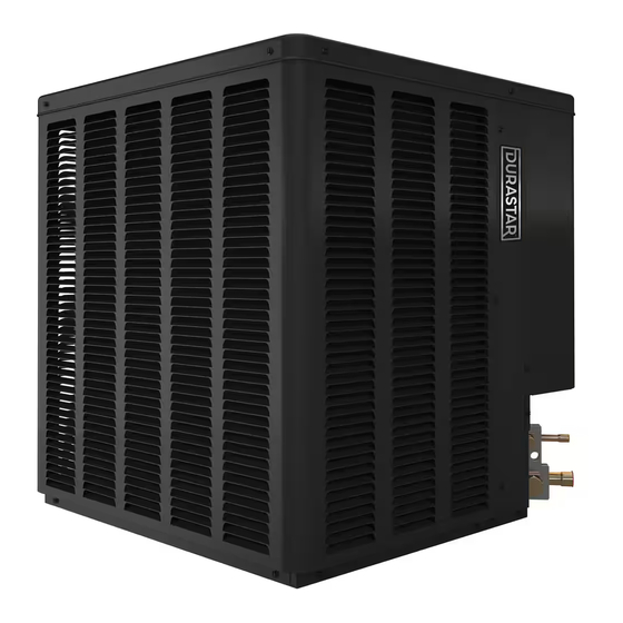
AIR COOLED
CONDENSING UNITS
INSTALLATION INSTRUCTIONS
DRAC16 MODEL SERIES
16 SEER
FEATURING INDUSTRY STANDARD
R-410A REFRIGERANT
NOTE: Actual unit appearance
may vary.
Advertisement
Table of Contents
Troubleshooting

Subscribe to Our Youtube Channel
Related Manuals for DURASTAR DRAC16 Series


Summary of Contents for DURASTAR DRAC16 Series
- Page 1 WARNING: AIR COOLED RECOGNIZE THIS SYMBOL AS AN INDICATION OF IMPORTANT SAFETY CONDENSING UNITS INFORMATION INSTALLATION INSTRUCTIONS WARNING THESE INSTRUCTIONS ARE INTENDED AS AN AID TO QUALIFIED, LICENSED DRAC16 MODEL SERIES SERVICE PERSONNEL FOR PROPER INSTALLATION, 16 SEER ADJUSTMENT, AND OPERATION OF THIS UNIT.
-
Page 2: Table Of Contents
CONTENTS 1.0 IMPORTANT SAFETY INFORMATION......3 5.3 Verify Indoor Air-Flow..............2.0 GENERAL INFORMATION..........4 5.4 Refrigerant Charging..............27 2.1 Introduction.................4 5.4.1 Measurement Device Set-Up..........27 2.2 Importance of a Quality Installation..........4 5.4.2 Preliminary Charging by Weight..........27 2.3 System Sizing and Selection............4 5.4.3 Preliminary Charging by Pressures........ -
Page 3: Important Safety Information
1.0 IMPORTANT SAFETY INFORMATION WARNINGS: CAUTIONS: • R-410A systems operate at approximately 60% • These instructions are intended as an aid to higher pressures (1.6 times) than R-22 systems. Do qualified, licensed service personnel for proper not use R-22 service equipment or components on installation, adjustment, and operation of this R-410A equipment. -
Page 4: General Information
2.0 GENERAL INFORMATION WARNING: • NFPA90A Installation of Air Conditioning and Ventilating Systems. Improper installation, or installation not made in • NFPA90B Installation of warm air heating and air accordance with these instructions, can result conditioning systems. in unsatisfactory operation and/or dangerous conditions and can cause the related warranty Install the indoor unit in such a way as to allow not to apply. -
Page 5: Importance Of Proper Indoor/Outdoor Match-Ups
2.0 GENERAL INFORMATION 2.4 Importance of 2.6 Efficiency Testing Proper Indoor/Outdoor Notice Match-Ups For purposes of verifying or testing efficiency ratings, the test procedure in Title 10 APPENDIX M To assure many years of reliable operation and to Subpart B of Part 430 (Uniform Test Method for optimum customer comfort and to assure the Measuring the Energy Consumption of Central Air outdoor unit warranty remains valid, an air-handler... -
Page 6: Unit Specifications
3.0 UNIT SPECIFICATIONS 3.1 Model Number Nomenclature 3.2 Available Models DRAC16A18AJ1NA DRAC16A24AJ1NA DRAC16A30AJ1NA DRAC16A36AJ1NA DRAC16A42BJ1NA DRAC16A48AJ1NA DRAC16A60AJ1NA... -
Page 7: Electrical And Physical Data
3.0 UNIT SPECIFICATIONS 3.3 Electrical and Physical Data ELECTRICAL DATA PHYSICAL DATA Fan Motor Minimum Compressor Fuse or HACR Outdoor Coil Weight Phase Refrig. Per Model Rated Load Locked Full Load Circuit Circuit Breaker Frequency (Hz) Face Area Circuit Shipping Number Amperes Rotor... - Page 8 3.0 UNIT SPECIFICATIONS 3.3 Electrical and Physical Data (cont.) AIR DISCHARGE: ALLOW FIGURE 1 60” [152.4 CM] MINIMUM DIMENSIONS CLEARANCE. A-00008 AIR INLETS (LOUVERED PANELS) ALLOW 6” [15.2 CM] MINIMUM CLEARANCE SERVICE ACCESS ALLOW 24” [61.0 cm] CLEARANCE NOTE: GRILLE APPEARANCE MAY VARY.
-
Page 9: Installation
4.0 INSTALLATION 4.1 Tools and Refrigerant 4.1.1 Tools Required for Pressure: The pressure of R-410A is approximately 60% (1.6 times) greater than Installing and Servicing R-22. Recovery and recycle equipment, pumps, R-410A Models hoses, and the like must have design pressure ratings appropriate for R-410A. -
Page 10: Choosing A Location
4.0 INSTALLATION 4.2 Choosing a Location 4.2.1 Allowable Clearances 4.2.2 Operational Issues Related to Unit Location 12" [30.5 cm] to side intake louvers 24" [61.0 cm] to service access panels IMPORTANT: 60" [152.4 cm] vertical for fan discharge Locate the unit If space limitations exist, the following clearances in a manner that will not prevent, impair, or will have minimal impact to capacity and efficiency... -
Page 11: Corrosive Environments
4.0 INSTALLATION 4.2 Choosing a Location (cont.) 4.2.3 Corrosive Environment WARNING: Disconnect all power to The metal parts of this unit may be subject to rust or unit before starting maintenance. Failure to do so can deterioration if exposed to a corrosive environment. cause electrical shock resulting in severe personal This oxidation could shorten the equipment’s useful injury or death. -
Page 12: Elevating Unit
4.0 INSTALLATION 4.3.3 Elevating Unit WARNING: Secure an elevated unit and its elevating stand in order to prevent tipping. Failure to do so may result in severe personal injury or death. If elevating the unit, either on a flat roof or on a slab, observe the following guidelines. -
Page 13: Refrigerant Line Set Selection
4.0 INSTALLATION 4.4 Refrigerant Line Set Selection 4.4.1 Replacing Existing Systems IMPORTANT: To prevent failure of a new unit, the existing line set When replacing an must be correctly sized for the new unit and must R-22 unit with an R-410A unit, either replace be cleaned or replaced. - Page 14 4.0 INSTALLATION 4.4 Refrigerant Line Set Selection (cont.) Table 2A: Refrigerant Line Sizing Chart (English Units) 16 SEER Single-Stage Air-Conditioners Apply Long Line Equivalent Length (Feet) Guidelines if Allowable Allowable Linear Line Length Unit Size Liquid Line Suction Line < 25 26-50 51-75 76-100...
- Page 15 4.0 INSTALLATION 4.5 Refrigerant Line Set Selection (cont.) Table 2B: Refrigerant Line Sizing Chart (Metric Units) 16 SEER Single-Stage Air-Conditioners Apply Long Line Equivalent Length (Meters) Guidelines if Allowable Allowable Linear Line Liquid Line Suction Line Unit Size Length Exceeds <...
-
Page 16: Suction Line Selection
4.0 INSTALLATION 4.4 Refrigerant Line Set Selection (cont.) 4.4.4 Suction Line Selection 4.4.5.2 Oil Return to Compressor Purpose of the suction line is to return superheated Small amounts of compressor crankcase oil is vapor to the condensing unit from the evaporator. picked up and carried out of the compressor by Proper suction line sizing is important because the moving refrigerant and is circulated through the... -
Page 17: Maximum Liquid Pressure Drop
4.0 INSTALLATION 4.4 Refrigerant Line Set Selection (cont.) 4.4.5.4 Maximum Liquid Pressure 4.4.5.6 Oil Level Adjustment for Drop Long Line Set Applications The total liquid line pressure drop must not exceed Additional oil may need to be added for long line set 50 psig [345 kPa] to assure a solid column of liquid at applications. -
Page 18: Line Set Installation
4.0 INSTALLATION 4.5 Line Set Installation • If tubing is to be run underground, it must be run in in the heating mode will result in noise inside the a sealed watertight chase. structure. • Use care in routing tubing and do not kink or twist. •... -
Page 19: Relative Location Of Indoor And Outdoor Units
4.0 INSTALLATION 4.5 Line Set Installation (cont.) 4.5.2 Relative Location of Indoor and Outdoor Units 4.5.2.1 Indoor and Outdoor Unit Near Same Level OUTDOOR UNIT LEVEL OR NEAR LEVEL TO INDOOR SECTION LINE SET REFERENCE TABLE 2 FOR MAXIMUM LENGTH LIMITATION IDEALLY, LINE SET SLOPES AWAY FROM OUTDOOR. -
Page 20: Outdoor Unit Below Indoor Unit
4.0 INSTALLATION 4.5 Line Set Installation (cont.) 4.5.2.2 Outdoor Unit Below Indoor Unit OUTDOOR UNIT BELOW INDOOR SECTION LINE SET ROUTE REFRIGERANT LINES EVEN WITH TOP OF COIL OR INSTALL INVERTED TRAP. INSULATE LIQUID LINE IN UNCONDITIONED INSULATE SUCTION SPACE FOR LONG LINE FULL LENGTH LINE APPLICATIONS FOR ALL APPLICATIONS... -
Page 21: Outdoor Unit Above Indoor Unit
4.0 INSTALLATION 4.5 Line Set Installation (cont.) 4.5.2.3 Outdoor Unit Above Indoor Unit INSULATE SUCTION LINE FULL LENGTH FOR ALL APPLICATIONS INSULATE LIQUID LINE IN UNCONDITIONED SPACE FOR LONG LINE APPLICATIONS REFERENCE TABLE 2 FOR MAXIMUM LENGTH AND VERTICAL SEPARATION LIMITATIONS VERIFY SUB-COOLING... -
Page 22: Tubing Connections
4.0 INSTALLATION 4.5 Line Set Installation (cont.) 4.5.3 Tubing Connections Indoor coils have only a holding charge of dry nitrogen. Keep all tube ends sealed until connections are to be made. • Use type “L” copper refrigeration tubing. Braze the connections with the following alloys: –... -
Page 23: Initial Leak Testing
4.0 INSTALLATION 4.6 Initial Leak Testing 4.7 Evacuation Indoor coils have only a holding charge of dry Evacuation is one of the most important parts of the nitrogen. Keep all tube ends sealed until connections entire installation and service procedure. The life and are to be made. -
Page 24: Control Wiring
4.0 INSTALLATION 4.9 Control Wiring WARNING: guide below to size the 24-volt control wiring. Turn off electric power Do not use phone cord to connect indoor and at the fuse box or service panel before making outdoor units and thermostat. This could damage any electrical connections. -
Page 25: Power Wiring
4.0 INSTALLATION 4.10 Typical Control Wiring Connections (cont.) 4.12 Grounding NOTICE: Field wiring must comply with the National Electric Code (C.E.C. in Canada) and any applicable local code. WARNING: The unit must be permanently grounded. Failure to do so can cause 4.11 Power Wiring electrical shock resulting in severe personal injury or death. -
Page 26: System Start-Up And Refrigerant Charging
5.0 SYSTEM START-UP & REFRIGERANT CHARGING 5.1 System Start-Up carefully. They must be sized and positioned to deliver treated air along the perimeter of the Overview space. If they are too small for their intended airflow, they become noisy. If they are not located Once the system hardware and wiring has been properly, drafts can result. -
Page 27: Refrigerant Charging
5.0 SYSTEM START-UP & REFRIGERANT CHARGING NOTICE: Gas furnaces can use: System maintenance is to be CFM = Output Capacity in BTUH* performed by a qualified and certified technician. SHC x temp rise The optimum refrigerant charge for any outdoor unit matched with an indoor coil/air handler is affected by the application. -
Page 28: Preliminary Charging By Pressures
5.0 SYSTEM START-UP & REFRIGERANT CHARGING Factory Charge for Line Set = 15 ft. × .6 oz. = 9 oz. [12.8°C] dry bulb and above Charge Adjustment = (1.2 oz. × 75 ft.) – 9 oz. + 3. Locate and note the design pressures. The 6 oz. -
Page 29: R-410A Temperature Pressure Chart
5.0 SYSTEM START-UP & REFRIGERANT CHARGING 5.4.5 R-410A Temperature located within 6" [15.2 cm] outside of the unit on the copper liquid line (small line). It is Pressure Chart recommended to use a calibrated clamp-on temperature probe or an insulated surface TEMPERATURE PRESSURE CHART SATURA- SATURA-... -
Page 30: Components & Controls
7.0 COMPONENTS & CONTROLS 7.1 Compressor Scroll compressors are used in all WA16 condens- ing units. 7.2 Fan Motor All WA16 condensing units are equipped with a standard PSC motor. 7.3 Outdoor Fan All heaters are located on the lower half of the compressor shell. -
Page 31: High And Low Pressure Control
7.0 COMPONENTS & CONTROLS 7.7 High- and Low-Pressure Controls (HPC and LPC) HPC and LPC are not factory installed, but can be field installed using the following kits: The low-pressure control (LPC) is an automatic- RXAB-A07 (High Pressure Control) reset which opens near 50 PSIG [345 kPa] and RXAC-A10 (Low Pressure Control) closes near 95 PSIG [655 kPa]. -
Page 32: Accessories
8.0 ACCESSORIES WARNING: be used on all equipment frequently operated Turn off electric power below 70°F [21°C] ambient. Part No. RXAD-A08 at the fuse box or service panel before making any electrical connections when installing accessories. 8.5 Compressor Failure to do so can result in electrical shock, severe personal injury, or death. -
Page 33: Diagnostics And Troubleshooting
9.0 DIAGNOSTICS & TROUBLESHOOTING 9.1 Cooling Mechanical Checks Flowchart... -
Page 34: General Troubleshooting Guide
9.0 DIAGNOSTICS & TROUBLESHOOTING 9.2 General Troubleshooting Guide WARNING: Disconnect all power to unit before servicing. Contactor may break only one side. Failure to shut off power can cause electrical shock resulting in personal injury or death. SYMPTOM POSSIBLE CAUSE REMEDY Unit will not run •... -
Page 35: Service Analyzer Charts
9.0 DIAGNOSTICS & TROUBLESHOOTING 9.3 Service Analyzer Charts COMPRESSOR OVERHEATING SYMPTOM POSSIBLE CAUSE CHECK/REMEDY High superheat (greater Low charge Check system charge. than 15°F [8.3°C] at coil) Faulty metering device Restricted cap tube, TXV Power element superheat out of adjustment internally Foreign matter stopping flow High internal load Hot air (attic) entering return... - Page 36 9.0 DIAGNOSTICS & TROUBLESHOOTING 9.3 Service Analyzer Charts (cont.) COMPRESSOR OVERHEATING (cont.) SYMPTOM POSSIBLE CAUSE CHECK OR REMEDIES Short cycling of Low charge Check system charge. compressor (cont.) Low evaporator airflow Dirty coil Dirty filter Duct too small or restricted Faulty run capacitor Replace.
- Page 37 9.0 DIAGNOSTICS & TROUBLESHOOTING 9.3 Service Analyzer Charts (cont.) CONTAMINATION SYMPTOM POSSIBLE CAUSE REMEDY Moisture Poor evacuation on installation or during service High head pressure Noncondensibles air Unusual head and Wrong refrigerant or mixed refrigerants suction readings Foreign matter – Copper tubing cuttings copper filings In each case, the cure is the same.
- Page 38 9.0 DIAGNOSTICS & TROUBLESHOOTING 9.3 Service Analyzer Charts (cont.) FLOODING SYMPTOM POSSIBLE CAUSE REMEDY Loose sensing bulb Secure the bulb and insulate. Bulb in wrong location Relocate bulb. Poor system control using a TXV Wrong size TXV Use correct replacement. Improper superheat setting (less than 5°F [2.8°C]) Replace TXV.
- Page 39 9.0 DIAGNOSTICS & TROUBLESHOOTING 9.3 Service Analyzer Charts (cont.) THERMOSTATIC EXPANSION VALVES (cont.) SYMPTOM POSSIBLE CAUSE REMEDY Refrigerant drainage from flooded evaporator Install trap riser to the top of the evaporator coil. Compressor flood Inoperable crankcase heater or crankcase heater Replace or add crankcase heater.
-
Page 40: Troubleshooting Tips
9.0 DIAGNOSTICS & TROUBLESHOOTING 9.4 Troubleshooting Tips COOLING MODE TROUBLESHOOTING TIPS INDICATORS DISCHARGE SUCTION SUPERHEAT COMPRESSOR SYSTEM SUBCOOLING PRESSURE PRESSURE Normal: AMPS PROBLEM Normal: See 5°–15°F Charging Chart [2.8° – 8.3°C] Overcharge High High High High Undercharge High Liquid Restriction High High (Filter Drier) -
Page 41: Outdoor Unit Maintenance
10.0 OUTDOOR UNIT MAINTENANCE 10.1 Outdoor Coil Cleaning The outdoor fan draws air across the coil during an angle. Washing from the top of the coil down operation which results in contaminants collecting from the inside out is the most effective method on and between the aluminum fins. -
Page 42: Wiring Diagram
11.0 WIRING DIAGRAM 90-101229-01 01-19-04...
Need help?
Do you have a question about the DRAC16 Series and is the answer not in the manual?
Questions and answers