Table of Contents
Advertisement
Quick Links
INSTALLATION MANUAL
ONE-WAY CASSETTE INDOOR UNIT
SPLIT-STYLE AIR CONDITIONER
DRAL06F1A, DRAL09F1A. DRAL12F1A, DRAL18F1A
Model Number:
Serial Number:
Purchase Date:
Installing Contractor Company Name:
TIP
Capture relevant information about your Durastar mini-split equipment before it is
installed and write it above for future reference.
1
DURASTAR.COM
Advertisement
Table of Contents

Subscribe to Our Youtube Channel
Related Manuals for DURASTAR DRAL12F1A


Summary of Contents for DURASTAR DRAL12F1A
- Page 1 ONE-WAY CASSETTE INDOOR UNIT SPLIT-STYLE AIR CONDITIONER DRAL06F1A, DRAL09F1A. DRAL12F1A, DRAL18F1A Model Number: Serial Number: Purchase Date: Installing Contractor Company Name: Capture relevant information about your Durastar mini-split equipment before it is installed and write it above for future reference. DURASTAR.COM...
-
Page 2: Table Of Contents
STEP 6: PREPARE REFRIGERANT PIPING ..................22 STEP 7: WRAP PIPES AND CABLE ...................... 23 STEP 8: ATTACH WATER RECEIVER .....................24 STEP 9: INSTALL PANEL ..........................25 STEP 10: COMPLETE A WATER DISCHARGE TEST ..............29 TROUBLESHOOTING ........................... 30 WIRING DIAGRAM ............................34 DURASTAR.COM... -
Page 3: Introduction
• Read the troubleshooting section of this manual as it will help you diagnose and solve common issues. • Visit us on the web at www.durastar.com to download product guides and up-to-date information. • If you need warranty service, our friendly customer service representatives are available via email at questions@durastar.com or by telephone at 1-888-320-0706. -
Page 4: Important Safety Precautions
Disconnect the power supply by turning it off at the circuit breaker when cleaning the air conditioner. Otherwise, you could risk electric shock. • Be careful when opening or closing valves below freezing temperatures. Refrigerant may spurt out from the gap between the valve stem and the valve body, resulting in injuries. DURASTAR.COM... - Page 5 • The air conditioner’s circuit board (PCB) is designed with a fuse to provide overcurrent protection. The specifications of the fuse are printed on the circuit board. DURASTAR.COM...
- Page 6 Do not climb onto or place objects on top of the outdoor unit. • Do not allow the air conditioner to operate for long periods of time with doors or windows open, or if the humidity is very high. DURASTAR.COM...
-
Page 7: Operating Temperatures
Regularly inspect and clean air filters. NOTE Your Durastar air conditioner's outdoor unit is equipped with a base pan heater, allowing it to continue to operate at freezing temperatures as low as -22°F (-30°C). When outdoor air temperatures are at or below 32°F (0°C), we strongly recommend keeping the unit plugged in at all times to ensure smooth ongoing performance. -
Page 8: Accessories
AAA Battery Cardboard Template Water Receiver Remote Control Holder Screw ST8*50 Remote Control Holder Mounting Screw Screw M4*22 Drain Pipe Adaptor Screw ST4.8*12 Copper Nut Screw ST3.9*10 Drain Joint Screw ST3.9*16 Drain Joint Seal Cable Tie Panel Rubber ring DURASTAR.COM... - Page 9 Indoor and outdoor connection wire • Outdoor power supply cord • Drain pipe • Pipe and cable wrapping tape • Wall hole sleeve and cover • Putty • Suspension bolts and necessary hardware to hang indoor unit • Wiring u-lugs DURASTAR.COM...
-
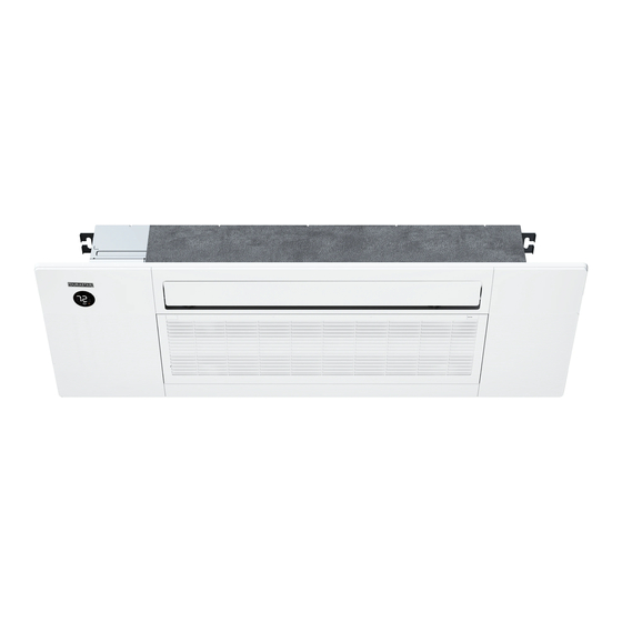
Page 10: Parts Identification
Air Vane Display Panel Display Panel Signal Cable, Air Inlets Refrigerant Pipes, and Drain Pipe Wiring Terminal Valve Cover Air Outlet NOTE Illustrations in this manual are for explanatory purposes. The actual shape of your mini-split equipment may vary slightly. DURASTAR.COM... -
Page 11: Unit Dimensions
UNIT DIMENSIONS 16-5/8" (423mm) 13-3/16" (335mm) 43-1/2" (1105mm) 53-1/2" (1360mm) DURASTAR.COM... -
Page 12: Installation Overview - Indoor Unit
INSTALLATION OVERVIEW - INDOOR UNIT Select Installation Location Install Ceiling Cassette Connect Wiring Prepare Drain Pipe Drill Wall Hole Connect Piping Wrap Piping and Cable Attach Water Receiver Install Panel Perform Water Discharge Test DURASTAR.COM... -
Page 13: Indoor Unit Installation
If there is no pre-existing piping, when choosing a location, leave ample room for a wall hole (See Step 5: Drill Wall Hole for Connective Piping). Think about the path the signal cable and refrigerant piping may take and if drilling joists may be necessary. DURASTAR.COM... - Page 14 Wall Ceiling >7-7/8" (200mm) air inlet air outlet Ceiling Hole DURASTAR.COM...
-
Page 15: Step 2: Install The One-Way Ceiling Cassette
2. With two (2) people, use the provided holes running along to the long sides of the cassette to screw the cassette to the ceiling joists. Use six (6) ST8.0*50 screws. NOTE The cassette fits between beams spaced 16" apart, with 1/2" allowance on both sides. DURASTAR.COM... - Page 16 Ceiling Bottom of unit ≤ 5/8 ” (16 mm) Ceiling board WARNING Ensure that the indoor unit is completely level. Improper installation can cause the drain pipe to back up into the unit and water leaks. DURASTAR.COM...
-
Page 17: Step 3: Connect Signal Wires To Indoor Unit
• Outdoor Power Cable: Determined by the amperage of system and the local codes in your area. CABLE SIZING Use a minimum of 14 AWG for power and signal cables connected to and between the indoor and outdoor units. DURASTAR.COM... - Page 18 To connect the signal wires to the indoor unit circuit breaker, do the following: 1. Remove the four (4) screws to open the indoor control box and the circuit breaker box. Four Screws Indoor Control Box Circuit Breaker Box DURASTAR.COM...
- Page 19 Three Knock-Out Holes (one hidden underneath) 3. Install the provided rubber ring in the hole to cover sharp sides. 4. Connect the wires to the breaker according to the wiring diagram. Ensure the ground wire is screwed in tightly. DURASTAR.COM...
- Page 20 If installing a wired thermostat, it is recommended to do that now before closing the breaker cover. Please see the wired thermostat instructions provided with the thermostat at www.durastar.com. 6. Install the breaker cover by replacing the two screws. DURASTAR.COM...
-
Page 21: Step 4: Connect Drain Pipe
1/2" (750mm) from the ceiling board. Install hanging wires every 3-5' to keep the drain pipe from sagging, and wrap the indoor portion of the pipe with foam pipe insulation to prevent condensation. Incorrect installation can cause water to flow back into the unit and leaks. DURASTAR.COM... -
Page 22: Step 5: Drill Wall Hole For Connective Piping
Refer to the Refrigerant Piping Connections section of the outdoor unit's installation manual for detailed instructions. WARNING Be extremely careful not to dent or damage the piping while bending them away from the unit. Any dents in the piping will affect the unit’s performance. DURASTAR.COM... -
Page 23: Step 7: Wrap Pipes And Cable
When wrapping the bundle, keep the ends of the piping unwrapped. You need to access them to test for leaks at the end of the installation process (refer to the Electrical and Gas Leak Checks section of the outdoor unit's installation manual). DURASTAR.COM... -
Page 24: Step 8: Attach Water Receiver
Attach the water receiver, supplied with the accessories, to the indoor unit using the ST4.8*12 screw. An extra ST4.8*12 screw is provided. Water Receiver NOTE Perform after connecting and wrapping the refrigeration tubing. See the instruction manual of the outdoor unit for details on connecting refrigeration tubing. DURASTAR.COM... -
Page 25: Step 9: Install Panel
2. Remove the two (2) screws. 3. Hold open the grille and push both latches toward the middle to unlock the grille. 4. Remove the grille panel. 5. Fix the panel to the one-way cassette by two (2) plastic buckles. Plastic buckle DURASTAR.COM... - Page 26 6. Manually rotate the air deflector and fix the panel to the cassette by using 3×M4*22 screws and a ST3.9*16 screw. NOTE: The ST3.9*16 screw is behind a cover. 7. Open the two covers on both sides of the panel , fix the panel to the cassette by using 3× M4*22 screws. DURASTAR.COM...
- Page 27 8. Connect the display board in the panel to the main control board. NOTE: Up to four wires are required. When wiring is complete, clip the wires together with the circled buckle. 9. Install the control box cover. Two screws for Circuit Breaker Two screws for Control Box DURASTAR.COM...
- Page 28 10. Close the two (2) plastic covers, located on both sides of the panel. 11. Reinstall the grille by pushing it into the latch to lock it. 12. Reinstall the two screws under the screw covers. Control box cover DURASTAR.COM...
-
Page 29: Step 10: Complete A Water Discharge Test
The drainage plug at the bottom of the unit body is used to discharge accumulated water from the drain pan when the air conditioner malfunctions. When the air conditioner is operating normally, make sure the drainage plug is properly plugged to prevent water from leaking. DURASTAR.COM... -
Page 30: Troubleshooting
The indoor unit makes A rushing air sound may occur when the louver resets its position. noises A squeaking sound may occur after running the unit in HEAT mode due to expansion and contraction of the unit’s plastic parts. DURASTAR.COM... - Page 31 • Press ON/OFF button on remote control to restart operation. NOTE If problem persists, contact a local dealer or your nearest customer service center. Provide them with a detailed description of the unit malfunction as well as your model number. DURASTAR.COM...
- Page 32 Incompressible gas or moisture has Evacuate and recharge the system with frequently entered the system. refrigerant. The compressor is broken. Replace the compressor. The voltage is too high or too low. Install a manostat to regulate the voltage. DURASTAR.COM...
- Page 33 If the problem persists, disconnect the power and contact your nearest appears customer service center. NOTE If your problem persists after performing the checks and diagnostics above, turn off your unit immediately and contact an authorized service center. DURASTAR.COM...
- Page 34 Low pressure protection PC03* Low temperature protection of outdoor unit PCOL Indoor units mode conflict ------- * NOTE The digital tube shows that DF / FC is in normal operation state, not fault or protection. * Applicable to only some units. DURASTAR.COM...
-
Page 35: Wiring Diagram
WIRING DIAGRAM DRAL06F1A, DRAL09F1A, DRAL12F1A, DRAL18F1A DURASTAR.COM... - Page 36 THIS PAGE INTENTIONALLY LEFT BLANK. DURASTAR.COM ©2022 Durastar V1.0 1122...
Need help?
Do you have a question about the DRAL12F1A and is the answer not in the manual?
Questions and answers