Table of Contents
Advertisement
Quick Links
INSTALLATION MANUAL
CEILING CASSETTE INDOOR UNIT
SPLIT-STYLE AIR CONDITIONER
DRAC24F1B
Model Number:
Serial Number:
Purchase Date:
Installing Contractor Company Name:
TIP
Capture relevant information about your Durastar mini-split equipment before it is
installed and write it above for future reference.
1
DURASTAR.COM
Advertisement
Chapters
Table of Contents
Troubleshooting

Subscribe to Our Youtube Channel
Related Manuals for DURASTAR DR3H48C121824


Summary of Contents for DURASTAR DR3H48C121824
- Page 1 INSTALLATION MANUAL CEILING CASSETTE INDOOR UNIT SPLIT-STYLE AIR CONDITIONER DRAC24F1B Model Number: Serial Number: Purchase Date: Installing Contractor Company Name: Capture relevant information about your Durastar mini-split equipment before it is installed and write it above for future reference. DURASTAR.COM...
-
Page 2: Table Of Contents
STEP 4: CONNECT DRAIN PIPE ............. 14 STEP 5: CONNECT SIGNAL CABLE ............ 15 STEP 6: PREPARE REFRIGERANT PIPING ........17 STEP 7: WRAP PIPES AND CABLE ............. 17 STEP 8: INSTALL PANEL ................18 TROUBLESHOOTING .................. 21 WIRING DIAGRAM ..................25 ERROR CODES ....................26 DURASTAR.COM... -
Page 3: Introduction
• Read the troubleshooting section of this manual as it will help you diagnose and solve common issues. • Visit us on the web at www.durastar.com to download product guides and up-to-date information. • If you need warranty service, our friendly customer service representatives are available via email at questions@durastar.com or by telephone at 1-888-320-0706. -
Page 4: Important Safety Precautions
Do not wash the air conditioner with water as this could cause an electric shock. • Disconnect the power supply by turning it off at the circuit breaker when cleaning the air conditioner. Otherwise, you could risk electric shock. DURASTAR.COM... - Page 5 • The air conditioner’s circuit board (PCB) is designed with a fuse to provide overcurrent protection. The specifications of the fuse are printed on the circuit board. DURASTAR.COM...
- Page 6 Do not climb onto or place objects on top of the outdoor unit. • Do not allow the air conditioner to operate for long periods of time with doors or windows open, or if the humidity is very high. DURASTAR.COM...
-
Page 7: Operating Temperatures
Regularly inspect and clean air filters. NOTE Your Durastar air conditioner's outdoor unit is equipped with a base pan heater, allowing it to continue to operate at freezing temperatures as low as -22°F (-30°C). When outdoor air temperatures are at or below 32°F (0°C), we strongly recommend keeping the unit plugged in at all times to ensure smooth ongoing performance. -
Page 8: Accessories
Indoor and outdoor connection wire • Outdoor power supply cord • Drain pipe • Pipe and cable wrapping tape • Wall hole sleeve and cover • Putty • Suspension bolts and necessary hardware to hang indoor unit • Wiring u-lugs DURASTAR.COM... -
Page 9: Tools Needed
Refrigerant leak detector • Copper pipe cutter • Flaring tool • Burr reamer • Crescent or spanner wrench • Hexagonal wrench set • Torque wrench • Multimeter • Electroprobe • Level • Hammer • Wire strippers • Wire crimper DURASTAR.COM... -
Page 10: Parts Identification
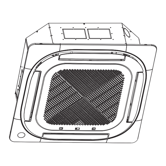
Remote Control Remote Control Holder Signal Cable, Air Inlets Refrigerant Pipes, and Drain Pipe Wiring Terminal Valve Cover Air Outlet NOTE Illustrations in this manual are for explanatory purposes. The actual shape of your mini-split equipment may vary slightly. DURASTAR.COM... -
Page 11: Installation Overview - Indoor Unit
INSTALLATION OVERVIEW - INDOOR UNIT Install the indoor unit Install the drain pipe Install the outdoor unit Connect the wires Evacuate and charge the Connect the refrigerant refrigeration system pipes Install the panel Perform a test run DURASTAR.COM... -
Page 12: Indoor Unit Installation
If there is no pre-existing refrigerant piping, when choosing a location, leave ample room for a wall hole (see Step 3: Drill Wall Hole for Connective Piping) for the signal cable and refrigerant piping that connect the indoor and outdoor units. DURASTAR.COM... -
Page 13: Step 2: Hang Indoor Unit
Ceiling Bottom of unit ≤ 5/8 - 1” (16 - 25mm) Ceiling board WARNING Ensure that the indoor unit is completely level. Improper installation can cause the drain pipe to back up into the unit and water leaks. DURASTAR.COM... -
Page 14: Step 3: Drill Wall Hole For Connective Piping
To keep the drain pipe from sagging, install hanging wires every 3-5'. Do not allow the drain pipe to bend or sag and trap condensation. 3’-5’ (1-1.5m) No bending Downward slope or sagging 1/100 DURASTAR.COM... -
Page 15: Step 5: Connect Signal Cable
1/8" (3mm) must be incorporated in the fixed wiring. A qualified technician must use an approved circuit breaker or switch. 7. Only connect the unit to an individual branch circuit outlet. Do not connect another appliance to that outlet. 8. Make sure to properly ground the air conditioner. DURASTAR.COM... -
Page 16: Cable Sizing
6. After checking to make sure every connection is secure, use the cable clamp to fasten the signal cable to the unit. Screw the cable clamp down tightly. 7. Replace the control box lid. DURASTAR.COM... -
Page 17: Step 6: Prepare Refrigerant Piping
Before passing the refrigerant piping, drain pipe, and the signal cable through the wall hole, you must bundle them together to save space, protect them, and insulate them. 1. Bundle the drain pipe, refrigerant pipes, and signal cable as shown below: Signal wire Refrigerant piping Insulation tape Drain pipe DURASTAR.COM... -
Page 18: Step 8: Install Panel
Release tabs 2. Remove the installation covers at each of the four corners in order to access the hooks on the main body when hanging the panel. Short ropes will keep the corners attached to the panel. Cover rope DURASTAR.COM... - Page 19 3/16"-1/4" (4-6mm). The edge of the panel should be in contact with the ceiling board. Unit body Ceiling board 3/16”-1/4” (4-6mm) Panel Panel foam 5. Carefully adjust the panel so that the ceiling opening is completely covered. DURASTAR.COM...
- Page 20 If necessary, the height can be adjusted by loosening the upper nut, and adjusting the lower nut at each of the corners. Make sure the internal wiring and drain pipe are not affected by this adjustment. 1-Loosen upper nut Gap not allowed 2-Adjust lower nut DURASTAR.COM...
-
Page 21: Troubleshooting
The indoor unit makes A rushing air sound may occur when the louver resets its position. noises A squeaking sound may occur after running the unit in HEAT mode due to expansion and contraction of the unit’s plastic parts. DURASTAR.COM... - Page 22 • Press ON/OFF button on remote control to restart operation. NOTE If problem persists, contact a local dealer or your nearest customer service center. Provide them with a detailed description of the unit malfunction as well as your model number. DURASTAR.COM...
- Page 23 Incompressible gas or moisture has Evacuate and recharge the system with quently entered the system. refrigerant. The compressor is broken. Replace the compressor. The voltage is too high or too low. Install a manostat to regulate the voltage. DURASTAR.COM...
- Page 24 If not, disconnect the power, then connect it again. Turn the unit on. appears If the problem persists, disconnect the power and contact your nearest customer service center. NOTE If your problem persists after performing the checks and diagnostics above, turn off your unit immediately and contact an authorized service center. DURASTAR.COM...
-
Page 25: Wiring Diagram
REMEMBER COOLING& VALUE NO_REMEMBER COOLING MODE MAIN HEATING ONLY MAIN MAIN SLAVE MODE Factory NO SLAVE Factory TO OUTDOOR UNIT Factory Setting Factory CAP1 Setting Setting Setting Dotted line indicates this component is 16022500005023 optional. Your configuration many vary. DURASTAR.COM... -
Page 26: Error Codes
Discharge high temperature Error PC60 Low pressure protection PC03 PC0L Low temperature protection of outdoor unit Indoor units mode con ict ---- Note: DF (defrost) and FC (forced cool) are normal operating states, not malfunctions. [ ] Applicable to some units only. DURASTAR.COM... - Page 27 THIS PAGE INTENTIONALLY LEFT BLANK. DURASTAR.COM...
- Page 28 THIS PAGE INTENTIONALLY LEFT BLANK. ©2022 Durastar DURASTAR.COM V1.1 1122...
- Page 29 MULTI-ZONE OUTDOOR UNIT SPLIT-STYLE AIR CONDITIONER DRA2U18M1B, DRA3U28M1B, DRA4U36M1B, DRA5U48M1B, DRA5U55M1B Model Number: Serial Number: Purchase Date: Installing Contractor Company Name: Capture relevant information about your Durastar mini-split equipment before it is installed and write it above for future reference. DURASTAR.COM...
- Page 30 STEP 2: REMOVE BURRS ..................... 17 STEP 3: FLARE PIPE ENDS ..................18 STEP 4: CONNECT PIPES ..................... 19 SYSTEM EVACUATION ....................20 FINAL CHECKS ........................22 TEST RUN ..........................23 TROUBLESHOOTING .....................24 WIRING DIAGRAMS ......................28 ERROR AND OPERATING CODES ................32 JOB SITE INFORMATION SHEET ................33 DURASTAR.COM...
-
Page 31: Introduction
• Read the troubleshooting section of this manual as it will help you diagnose and solve common issues. • Visit us on the web at WWW.DURASTAR.COM to download product guides and up-to-date information. • If you need warranty service, our friendly customer service representatives are available via email at QUESTIONS@DURASTAR.COM or by telephone at 1-888-320-0706. -
Page 32: Important Safety Precautions
Do not wash the air conditioner with water as this could cause an electric shock. • Disconnect the power supply by turning it off at the circuit breaker when cleaning the air conditioner. Otherwise, you could risk electric shock. DURASTAR.COM... - Page 33 • The air conditioner’s circuit board (PCB) is designed with a fuse to provide over-current protection. The specifications of the fuse are printed on the circuit board. DURASTAR.COM...
- Page 34 Do not climb onto or place objects on top of the outdoor unit. • Do not allow the air conditioner to operate for long periods of time with doors or windows open, or if the humidity is very high. DURASTAR.COM...
-
Page 35: Operating Temperatures
Regularly inspect and clean air filters. NOTE Your Durastar air conditioner's outdoor unit is equipped with a base pan heater, allowing it to continue to operate at freezing temperatures as low as -13°F (-25°C). When outdoor air temperatures are at or below 32°F (0°C), we strongly recommend keeping the unit plugged in at all times to ensure smooth ongoing performance. -
Page 36: Accessories
• Wire strippers • HVAC manifold gauge set • Wire crimper • Micron Gauge • Multimeter • Refrigerant leak detector • Electroprobe • Copper pipe cutter • Level • Flaring tool • Burr reamer • Crescent or spanner wrench DURASTAR.COM... -
Page 37: Parts Identification
Drain Pipe Air Inlets Power Supply Wiring Terminal Refrigerant Valves Air Outlet NOTE Illustrations in this manual are for explanatory purposes. The actual shape of your mini- split equipment may vary slightly. Indoor units may also vary in configuration. DURASTAR.COM... -
Page 38: Outdoor Unit Installation
Near animals or plants that will be harmed by hot air discharge. • Near any source of combustible gas. • In a location that is exposed to large amounts of dust. • In a location exposed to an excessive amount of salty air. DURASTAR.COM... -
Page 39: Step 2: Install The Drain Joint
(M10). Mount the unit on a cement slab, condenser mounting pad, or other level surface able to support the unit's weight. Do not place the unit directly on the ground. If using a wall- mounting bracket, make sure the attached structure can support at least four times the unit's weight. DURASTAR.COM... - Page 40 L = Wall / Obstruction height A = Required distance between unit and wall / obstruction L ≤ 1/2H ≥9 13/16” (250mm) L ≤ H 1/2H < L ≤ H ≥11 13/16” (300mm) L > H Can not be installed DURASTAR.COM...
-
Page 41: Step 4: Connect The Signal And Power Cables
Before performing any electrical or wiring work, turn off the main power to the system. USE THE RIGHT CABLE • Indoor Power/ Signal Cable: 14/4 stranded, unshielded • Outdoor Power Cable: Determined by amperage of system and the local codes in your area. DURASTAR.COM... - Page 42 8. Replace the wire cover on the side of the unit, and screw it in place. Terminal block Connecting cable Power supply cord Conduit panel Wire Cover Select the appropriate holes to feed the wires through according to their diameter. DURASTAR.COM...
-
Page 43: Refrigerant Piping Connections
Perform leak check procedures. Afterwards, remove the high side hose and attach the low side hose from the manifold to evacuate all connected zones. DURASTAR.COM... -
Page 44: Oil Traps
Indoor Unit 19’ 9” (6m) 32’ 10” (10m) Required distance between oil traps when Required distance between oil traps when the indoor unit is installed higher than the the outdoor unit is installed higher than the outdoor unit. indoor unit. DURASTAR.COM... -
Page 45: Step 1: Cut Pipes
Burrs can affect the airtight seal of the refrigerant piping connection and must be completely removed. 1. Hold the pipe at a downward angle to prevent burrs from falling into the pipe. 2. Using a reamer or deburring tool, remove all burrs from the cut section of the pipe. Pipe Reamer Point downward DURASTAR.COM... -
Page 46: Step 3: Flare Pipe Ends
0.04" (1.0mm) 0.07" (1.8mm) Ø 5/8" (15.9mm) 0.078" (2.0mm) 0.086" (2.2mm) Ø 3/4" (19.1mm) 0.078" (2.0mm) 0.094" (2.4mm) Flare form TIP: THICKNESS COMPARISON • 0.0275" = A Thumbnail • 0.04" = A Dime • 0.078" = A Nickle Pipe DURASTAR.COM... -
Page 47: Step 4: Connect Pipes
4. While firmly gripping the nut on the unit tubing, use a torque wrench to tighten the flare nut according to the torque values in the table on the next page. Loosen the flaring nut slightly, then tighten again. DURASTAR.COM... -
Page 48: System Evacuation
Use a vacuum pump and manifold gauge to evacuate the refrigerant system, removing any non-condensible gas and moisture from the system. Evacuation should be performed upon initial installation and if unit is relocated. DURASTAR.COM... - Page 49 Do not try to force the valves to open further. Manifold Gauge Low pressure Flare nut gauge Low pressure High pressure valve valve Low pressure hose Auxiliary hose Vacuum pump Valve body Valve stem Low pressure valve DURASTAR.COM...
-
Page 50: Final Checks
The refrigerant should be charged from the service port on the outdoor unit's low pressure valve. Additional refrigerant information can be found in the SUBMITTALS DOCUMENTS at WWW.SERVICE.DURASTAR.COM. Additional refrigerant can be calculated using the following formula: Liquid Side Ø 1/4" (6.35mm) Liquid Side Ø... -
Page 51: Test Run
A: Low pressure stop valve B: High pressure stop valve C & D: Indoor unit flare nuts Use the Durastar Job Site Information Sheet at the end of this manual as a commissioning report to record your start up readings. TEST RUN TEST RUN INSTRUCTIONS You should perform the test run for at least 30 minutes. -
Page 52: Troubleshooting
The indoor unit makes A rushing air sound may occur when the louver resets its position. noises A squeaking sound may occur after running the unit in HEAT mode due to expansion and contraction of the unit’s plastic parts. DURASTAR.COM... - Page 53 • Press ON/OFF button on remote control to restart operation. NOTE If problem persists, contact a local dealer or your nearest customer service center. Provide them with a detailed description of the unit malfunction as well as your model number. DURASTAR.COM...
- Page 54 Incompressible gas or moisture has Evacuate and recharge the system with quently entered the system refrigerant The compressor is broken Replace the compressor The voltage is too high or too low Install a manostat to regulate the voltage DURASTAR.COM...
- Page 55 If not, disconnect the power, then connect it again. Turn the unit on. appears If the problem persists, disconnect the power and contact your nearest customer service center. NOTE If your problem persists after performing the checks and diagnostics above, turn off your unit immediately and contact an authorized service center. DURASTAR.COM...
-
Page 56: Wiring Diagrams
WIRING DIAGRAMS DRA2U18M1B COMP TOP 5(8) Dotted line indicates this component is optional. Your configuration many vary. 16022000035644 DURASTAR.COM... - Page 57 DRA3U28M1B Dotted line indicates this component is optional. Your configuration many vary. 16022300002514 DURASTAR.COM...
- Page 58 DRA4U36M1B Dotted line indicates this component is optional. Your configuration many vary. 16022300002633 DURASTAR.COM...
- Page 59 DRA5U48M1B and DRA5U55M1B IPM&PFC BOARD MAIN CONTROL BOARD INDOOR COIL OUTLET TEMP.SENSOR Dotted line indicates this component is optional. Your configuration many vary. 16022000036851 DURASTAR.COM...
-
Page 60: Error And Operating Codes
High temperature protection of Evaporator PH91 Low temperature protection of Evaporator LC06 High temperature protection of Inverter module (IPM) Note: DF (defrost) and FC (forced cooling) are normal operating codes, not malfunctions. [ ] Applicable to some units only. DURASTAR.COM... -
Page 61: Job Site Information Sheet
Line Voltage (Power Off): L1 to L2 _____________ L1 to G _____________ L2 to G ________________ Line Voltage (Power On): L1 to L2 _____________ L1 to G _____________ L2 to G ________________ Outdoor Thermal Readings Discharge: _________°F Ambient: _________°F DURASTAR.COM... - Page 62 (Circle Liquid and Gas Line): Electrical Readings Power/Control Wire Color: 1 _______________ 2 _______________ 3 ________________ Voltage Readings: 1-2 ___________ AC 2-3 ___________DC Thermal Readings Return Air: _________°F Supply Air: _________°F Room Air: _________°F Gas Line Saturation: _________°F Liquid Line Saturation: _________°F DURASTAR.COM...
- Page 63 (Circle Liquid and Gas Line): Electrical Readings Power/Control Wire Color: 1 _______________ 2 _______________ 3 ________________ Voltage Readings: 1-2 ___________ AC 2-3 ___________DC Thermal Readings Return Air: _________°F Supply Air: _________°F Room Air: _________°F Gas Line Saturation: _________°F Liquid Line Saturation: _________°F DURASTAR.COM...
- Page 64 (Circle Liquid and Gas Line): Electrical Readings Power/Control Wire Color: 1 _______________ 2 _______________ 3 ________________ Voltage Readings: 1-2 ___________ AC 2-3 ___________DC Thermal Readings Return Air: _________°F Supply Air: _________°F Room Air: _________°F Gas Line Saturation: _________°F Liquid Line Saturation: _________°F DURASTAR.COM...
- Page 65 NOTES: DURASTAR.COM...
- Page 66 THIS PAGE INTENTIONALLY LEFT BLANK. DURASTAR.COM...
- Page 67 THIS PAGE INTENTIONALLY LEFT BLANK. DURASTAR.COM...
- Page 68 THIS PAGE INTENTIONALLY LEFT BLANK. ©2022 Durastar DURASTAR.COM V2.0 1122...
- Page 69 CEILING CASSETTE INDOOR UNIT SPLIT-STYLE AIR CONDITIONER DRAC09F1A, DRAC12F1A, DRAC18F1A, DRAC24F1A Model Number: Serial Number: Purchase Date: Installing Contractor Company Name: Capture relevant information about your Durastar mini-split equipment before it is installed and write it above for future reference. DURASTAR.COM...
- Page 70 STEP 3: DRILL WALL HOLE FOR CONNECTIVE PIPING ............. 15 STEP 4: CONNECT DRAIN PIPE ......................16 STEP 5: CONNECT SIGNAL CABLE ....................17 STEP 6: PREPARE REFRIGERANT PIPING .................. 19 STEP 7: WRAP PIPES AND CABLE ....................19 STEP 8: INSTALL PANEL ........................20 TROUBLESHOOTING ..........................24 DURASTAR.COM...
-
Page 71: Introduction
• Read the troubleshooting section of this manual as it will help you diagnose and solve common issues. • Visit us on the web at www.durastar.com to download product guides and up-to-date information. • If you need warranty service, our friendly customer service representatives are available via email at questions@durastar.com or by telephone at 1-888-320-0706. -
Page 72: Important Safety Precautions
Do not wash the air conditioner with water as this could cause an electric shock. • Disconnect the power supply by turning it off at the circuit breaker when cleaning the air conditioner. Otherwise, you could risk electric shock. DURASTAR.COM... - Page 73 • The air conditioner’s circuit board (PCB) is designed with a fuse to provide overcurrent protection. The specifications of the fuse are printed on the circuit board. DURASTAR.COM...
- Page 74 Do not climb onto or place objects on top of the outdoor unit. • Do not allow the air conditioner to operate for long periods of time with doors or windows open, or if the humidity is very high. DURASTAR.COM...
-
Page 75: Operating Temperatures
Regularly inspect and clean air filters. NOTE Your Durastar air conditioner's outdoor unit is equipped with a base pan heater, allowing it to continue to operate at freezing temperatures as low as -13°F (-25°C). When outdoor air temperatures are at or below 32°F (0°C), we strongly recommend keeping the unit plugged in at all times to ensure smooth ongoing performance. -
Page 76: Accessories
Indoor and outdoor connection wire • Outdoor power supply cord • Drain pipe • Pipe and cable wrapping tape • Wall hole sleeve and cover • Putty • Suspension bolts and necessary hardware to hang indoor unit • Wiring u-lugs DURASTAR.COM... - Page 77 Refrigerant leak detector • Copper pipe cutter • Flaring tool • Burr reamer • Crescent or spanner wrench • Hexagonal wrench set • Torque wrench • Multimeter • Electroprobe • Level • Hammer • Wire strippers • Wire crimper DURASTAR.COM...
-
Page 78: Parts Identification
Wiring Terminal Air Outlet Panel Refrigerant Pipes Valve Cover Air Inlet Remote Control Air Inlet Control Panel Drain Pipe Air Outlet NOTE Illustrations in this manual are for explanatory purposes. The actual shape of your mini-split equipment may vary slightly. DURASTAR.COM... -
Page 79: Installation Overview - Indoor Unit
INSTALLATION OVERVIEW - INDOOR UNIT Install the indoor unit Install the drain pipe Install the outdoor unit Connect the wires Evacuate and charge the Connect the refrigerant refrigeration system pipes Install the panel Perform a test run DURASTAR.COM... -
Page 80: Indoor Unit Installation
Near any source of heat, steam, or combustible gas • Near flammable items such as curtains or clothing • Near any obstacle that might block air circulation • Near a doorway • In a location subject to direct sunlight DURASTAR.COM... - Page 81 If there is no pre-existing refrigerant piping, when choosing a location, leave ample room for a wall hole (see Step 3: Drill Wall Hole for Connective Piping) for the signal cable and refrigerant piping that connect the indoor and outdoor units. DURASTAR.COM...
-
Page 82: Step 2: Hang Indoor Unit
2. Drill four holes 2" deep in the internal ceiling for each of the required suspension bolt anchors (field supplied). Make sure to hold the drill at a 90o angle to the ceiling. 3. Using a hammer, insert the suspension bolt anchors into the pre-drilled holes. 4. Install the four suspension bolts. DURASTAR.COM... -
Page 83: Step 3: Drill Wall Hole For Connective Piping
After the sleeve is inserted through the wall, connect the wall hole sleeve cover to the wall sleeve on the outside end. Make sure the cover is flush with the outside wall. DURASTAR.COM... -
Page 84: Step 4: Connect Drain Pipe
Incorrect installation can cause water to flow back into the unit and leaks. Ceiling 39-59” ≤11 3/4” (300mm) (1-1.5m) ≤20 7/8” (530mm) ≤29 1/2” (750mm) 8 5/8” (220mm) 0-3” (0-75mm) DURASTAR.COM... -
Page 85: Step 5: Connect Signal Cable
12. To avoid getting an electric shock, never touch the electrical components soon after the power supply has been turned off. After turning off the power, always wait 10 minutes or more before you touch the electrical components. WARNING Before performing any electrical or wiring work, turn off the main power to the system. DURASTAR.COM... - Page 86 6. After checking to make sure every connection is secure, use the cable clamp to fasten the signal cable to the unit. Screw the cable clamp down tightly. 7. Replace the control box lid. WARNING All wiring must be performed strictly in accordance with the wiring diagram located on the inside of the control box lid. DURASTAR.COM...
-
Page 87: Step 6: Prepare Refrigerant Piping
Drain pipe NOTE The drain pipe MUST be at the bottom of the bundle. Putting the drain pipe at the top of the bundle can cause the drain pan to overflow, which can lead to fire or water damage. DURASTAR.COM... -
Page 88: Step 8: Install Panel
2. Install the main panel body by aligning the arrow on the panel to the arrow on the unit. Attach the panel body to the unit with the supplied screws as shown below. Main panel body Screws (M5 - supplied with the panel) DURASTAR.COM... - Page 89 5. Remove the control box lid and connect the two cables from the main panel body to the main board on the unit. 5-core wire 10-core wire 6. Replace the control box lid with its screws and close the inner panel making sure it latches securely in place. DURASTAR.COM...
- Page 90 3/16 - 1/4". The edge of the panel should be in contact with the ceiling board. Adjust the panel so that the ceiling opening is completely covered. Latch Piping side Drain side Screwdriver DURASTAR.COM...
- Page 91 If necessary, the height can be adjusted by loosening the upper nut, and adjusting the lower nut at each of the corners. Make sure the internal wiring and drain pipe are not affected by this adjustment. 1-Loosen upper nut Gap not allowed 2-Adjust lower nut DURASTAR.COM...
-
Page 92: Troubleshooting
The indoor unit makes A rushing air sound may occur when the louver resets its position. noises A squeaking sound may occur after running the unit in HEAT mode due to expansion and contraction of the unit’s plastic parts. DURASTAR.COM... - Page 93 • Press ON/OFF button on remote control to restart operation. NOTE If problem persists, contact a local dealer or your nearest customer service center. Provide them with a detailed description of the unit malfunction as well as your model number. DURASTAR.COM...
- Page 94 Incompressible gas or moisture has Evacuate and recharge the system with entered the system refrigerant The compressor is broken Replace the compressor The voltage is too high or too low Install a manostat to regulate the voltage DURASTAR.COM...
- Page 95 If the problem persists, disconnect the power and contact your nearest customer appears service center. NOTE If your problem persists after performing the checks and diagnostics above, turn off your unit immediately and contact an authorized service center. DURASTAR.COM...
- Page 96 ©2021 Durastar DURASTAR.COM V1.1 0421...
- Page 97 CEILING CASSETTE INDOOR UNIT SPLIT-STYLE AIR CONDITIONER DRAC09F1A, DRAC12F1A, DRAC18F1A, DRAC24F1A Model Number: Serial Number: Purchase Date: Installing Contractor Company Name: Capture relevant information about your Durastar mini-split equipment before it is installed and write it above for future reference. DURASTAR.COM...
- Page 98 STEP 3: DRILL WALL HOLE FOR CONNECTIVE PIPING ............. 15 STEP 4: CONNECT DRAIN PIPE ......................16 STEP 5: CONNECT SIGNAL CABLE ....................17 STEP 6: PREPARE REFRIGERANT PIPING .................. 19 STEP 7: WRAP PIPES AND CABLE ....................19 STEP 8: INSTALL PANEL ........................20 TROUBLESHOOTING ..........................24 DURASTAR.COM...
-
Page 99: Introduction
• Read the troubleshooting section of this manual as it will help you diagnose and solve common issues. • Visit us on the web at www.durastar.com to download product guides and up-to-date information. • If you need warranty service, our friendly customer service representatives are available via email at questions@durastar.com or by telephone at 1-888-320-0706. -
Page 100: Important Safety Precautions
Do not wash the air conditioner with water as this could cause an electric shock. • Disconnect the power supply by turning it off at the circuit breaker when cleaning the air conditioner. Otherwise, you could risk electric shock. DURASTAR.COM... - Page 101 • The air conditioner’s circuit board (PCB) is designed with a fuse to provide overcurrent protection. The specifications of the fuse are printed on the circuit board. DURASTAR.COM...
- Page 102 Do not climb onto or place objects on top of the outdoor unit. • Do not allow the air conditioner to operate for long periods of time with doors or windows open, or if the humidity is very high. DURASTAR.COM...
-
Page 103: Operating Temperatures
Regularly inspect and clean air filters. NOTE Your Durastar air conditioner's outdoor unit is equipped with a base pan heater, allowing it to continue to operate at freezing temperatures as low as -13°F (-25°C). When outdoor air temperatures are at or below 32°F (0°C), we strongly recommend keeping the unit plugged in at all times to ensure smooth ongoing performance. -
Page 104: Accessories
Indoor and outdoor connection wire • Outdoor power supply cord • Drain pipe • Pipe and cable wrapping tape • Wall hole sleeve and cover • Putty • Suspension bolts and necessary hardware to hang indoor unit • Wiring u-lugs DURASTAR.COM... - Page 105 Refrigerant leak detector • Copper pipe cutter • Flaring tool • Burr reamer • Crescent or spanner wrench • Hexagonal wrench set • Torque wrench • Multimeter • Electroprobe • Level • Hammer • Wire strippers • Wire crimper DURASTAR.COM...
-
Page 106: Parts Identification
Wiring Terminal Air Outlet Panel Refrigerant Pipes Valve Cover Air Inlet Remote Control Air Inlet Control Panel Drain Pipe Air Outlet NOTE Illustrations in this manual are for explanatory purposes. The actual shape of your mini-split equipment may vary slightly. DURASTAR.COM... -
Page 107: Installation Overview - Indoor Unit
INSTALLATION OVERVIEW - INDOOR UNIT Install the indoor unit Install the drain pipe Install the outdoor unit Connect the wires Evacuate and charge the Connect the refrigerant refrigeration system pipes Install the panel Perform a test run DURASTAR.COM... -
Page 108: Indoor Unit Installation
Near any source of heat, steam, or combustible gas • Near flammable items such as curtains or clothing • Near any obstacle that might block air circulation • Near a doorway • In a location subject to direct sunlight DURASTAR.COM... - Page 109 If there is no pre-existing refrigerant piping, when choosing a location, leave ample room for a wall hole (see Step 3: Drill Wall Hole for Connective Piping) for the signal cable and refrigerant piping that connect the indoor and outdoor units. DURASTAR.COM...
-
Page 110: Step 2: Hang Indoor Unit
2. Drill four holes 2" deep in the internal ceiling for each of the required suspension bolt anchors (field supplied). Make sure to hold the drill at a 90o angle to the ceiling. 3. Using a hammer, insert the suspension bolt anchors into the pre-drilled holes. 4. Install the four suspension bolts. DURASTAR.COM... -
Page 111: Step 3: Drill Wall Hole For Connective Piping
After the sleeve is inserted through the wall, connect the wall hole sleeve cover to the wall sleeve on the outside end. Make sure the cover is flush with the outside wall. DURASTAR.COM... -
Page 112: Step 4: Connect Drain Pipe
Incorrect installation can cause water to flow back into the unit and leaks. Ceiling 39-59” ≤11 3/4” (300mm) (1-1.5m) ≤20 7/8” (530mm) ≤29 1/2” (750mm) 8 5/8” (220mm) 0-3” (0-75mm) DURASTAR.COM... -
Page 113: Step 5: Connect Signal Cable
12. To avoid getting an electric shock, never touch the electrical components soon after the power supply has been turned off. After turning off the power, always wait 10 minutes or more before you touch the electrical components. WARNING Before performing any electrical or wiring work, turn off the main power to the system. DURASTAR.COM... - Page 114 6. After checking to make sure every connection is secure, use the cable clamp to fasten the signal cable to the unit. Screw the cable clamp down tightly. 7. Replace the control box lid. WARNING All wiring must be performed strictly in accordance with the wiring diagram located on the inside of the control box lid. DURASTAR.COM...
-
Page 115: Step 6: Prepare Refrigerant Piping
Drain pipe NOTE The drain pipe MUST be at the bottom of the bundle. Putting the drain pipe at the top of the bundle can cause the drain pan to overflow, which can lead to fire or water damage. DURASTAR.COM... -
Page 116: Step 8: Install Panel
2. Install the main panel body by aligning the arrow on the panel to the arrow on the unit. Attach the panel body to the unit with the supplied screws as shown below. Main panel body Screws (M5 - supplied with the panel) DURASTAR.COM... - Page 117 5. Remove the control box lid and connect the two cables from the main panel body to the main board on the unit. 5-core wire 10-core wire 6. Replace the control box lid with its screws and close the inner panel making sure it latches securely in place. DURASTAR.COM...
- Page 118 3/16 - 1/4". The edge of the panel should be in contact with the ceiling board. Adjust the panel so that the ceiling opening is completely covered. Latch Piping side Drain side Screwdriver DURASTAR.COM...
- Page 119 If necessary, the height can be adjusted by loosening the upper nut, and adjusting the lower nut at each of the corners. Make sure the internal wiring and drain pipe are not affected by this adjustment. 1-Loosen upper nut Gap not allowed 2-Adjust lower nut DURASTAR.COM...
-
Page 120: Troubleshooting
The indoor unit makes A rushing air sound may occur when the louver resets its position. noises A squeaking sound may occur after running the unit in HEAT mode due to expansion and contraction of the unit’s plastic parts. DURASTAR.COM... - Page 121 • Press ON/OFF button on remote control to restart operation. NOTE If problem persists, contact a local dealer or your nearest customer service center. Provide them with a detailed description of the unit malfunction as well as your model number. DURASTAR.COM...
- Page 122 Incompressible gas or moisture has Evacuate and recharge the system with entered the system refrigerant The compressor is broken Replace the compressor The voltage is too high or too low Install a manostat to regulate the voltage DURASTAR.COM...
- Page 123 If the problem persists, disconnect the power and contact your nearest customer appears service center. NOTE If your problem persists after performing the checks and diagnostics above, turn off your unit immediately and contact an authorized service center. DURASTAR.COM...
- Page 124 ©2021 Durastar DURASTAR.COM V1.1 0421...
Need help?
Do you have a question about the DR3H48C121824 and is the answer not in the manual?
Questions and answers