Table of Contents
Advertisement
Quick Links
GA800 DRIVE
I N S T A L L A T I O N M A N U A L
I P 5 5 / U L T Y P E 1 2 H E A T S I N K E X T E R N A L
M O U N T I N G
C A T A L O G C O D E :
PDF
GA80Uxxxxxxxx
yaskawa.com/TOEPC71061779
C A P A C I T I E S :
Three-Phase 240 V Class: 1 to 150 HP
Three-Phase 480 V Class: 1 to 600 HP
Three-Phase 600 V Class: 125 to 500 HP
6-Phase/12-Pulse 400 V Class: 75 to 600 HP
D O C U M E N T N U M B E R : T O E P C 7 1 0 6 1 7 7 9
Advertisement
Table of Contents

Related Manuals for YASKAWA GA800 GA80U Series


Summary of Contents for YASKAWA GA800 GA80U Series
- Page 1 M O U N T I N G C A T A L O G C O D E : GA80Uxxxxxxxx yaskawa.com/TOEPC71061779 C A P A C I T I E S : Three-Phase 240 V Class: 1 to 150 HP...
- Page 2 This Page Intentionally Blank YASKAWA TOEPC71061779E GA800 DRIVE INSTALLATION MANUAL...
-
Page 3: Table Of Contents
Gasket Models ........... . . 38 YASKAWA TOEPC71061779E GA800 DRIVE INSTALLATION MANUAL... - Page 4 Revision History ........... . . 96 YASKAWA TOEPC71061779E GA800 DRIVE INSTALLATION MANUAL...
-
Page 5: Preface And General Precautions
Failure to obey these precautions can cause serious injury or death, or damage to the product or related devices and systems. Yaskawa must not be held responsible for any injury or equipment damage as a result of the failure to observe these precautions and instructions. -
Page 6: Overview
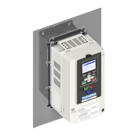
1.1 Overview Overview An IP55/UL Type 12 Heatsink External Mounting drive lets you install the drive in a Type 12 enclosure or panel with the heatsink external and keep the Type 12 rating. YASKAWA TOEPC71061779E GA800 DRIVE INSTALLATION MANUAL... -
Page 7: Applicable Documentation
The manuals also include important information about parameter settings and tuning the drive. GA800 Series You can download drive manuals from the Yaskawa product and technical information website shown on the back cover of this manual. AC Drive for Industrial Applications... -
Page 8: Safety
WARNING! Electrical Shock Hazard. Do not modify the drive body or drive circuitry. Modifications to drive body and circuitry can cause serious injury or death, will cause damage to the drive, and will void the warranty. Yaskawa is not responsible for modifications of the product made by the user. - Page 9 If you do not know the cause of the problem, contact Yaskawa before you energize the drive or peripheral devices. If you do not fix the problem before you operate the drive or peripheral devices, it can cause serious injury or death.
-
Page 10: Warning Label Content And Location
Warning Label Content and Location The drive warning label is in the location shown in Figure 1.1. Use the drive as specified by this information. A - Warning label Figure 1.1 Warning Label Content and Location YASKAWA TOEPC71061779E GA800 DRIVE INSTALLATION MANUAL... -
Page 11: Receiving
1. Inspect the product for damage and missing parts. Immediately contact the shipping company if the drive is damaged. The Yaskawa warranty does not cover damage from shipping. 2. Check the catalog code in the "C/C" section of the drive nameplate to make sure that you received the correct model. - Page 12 J - Output specifications Yaskawa Electric Corporation K - Input specifications E - Standards compliance L - Catalog code F - Surrounding air temperature Figure 2.1 Nameplate Example How to Read the Catalog Code..................13 YASKAWA TOEPC71061779E GA800 DRIVE INSTALLATION MANUAL...
-
Page 13: How To Read The Catalog Code
• A: IP00/UL Open Type • B: IP20/UL Open Type • F: IP20/UL Type 1 • T: IP55/UL Type 12 • W: IP55/UL Type 12 Heatsink External Mounting Environmental specification • M: Resistant to dust/humidity YASKAWA TOEPC71061779E GA800 DRIVE INSTALLATION MANUAL... - Page 14 2.1 How to Read the Catalog Code YASKAWA TOEPC71061779E GA800 DRIVE INSTALLATION MANUAL...
-
Page 15: Mechanical Installation
IP55/UL Type 12 Heatsink External Mounting Drive Dimensions....18 Panel Cut-Out Dimensions (IP55/UL Type 12 Heatsink External Mounting) ........................24 Estimated Weights (IP55/UL Type 12 Heatsink External Mounting) .... 29 Install the Gasket...................... 31 Installation Procedure..................... 32 Gasket Models......................38 YASKAWA TOEPC71061779E GA800 DRIVE INSTALLATION MANUAL... -
Page 16: Installation Environment
• Installing the drive between 2000 m to 4000 m (6562 ft to 13123 ft) and grounding the neutral point on the power supply. Contact Yaskawa or your nearest sales representative when not grounding the neutral point. • 10 Hz to 20 Hz: 1 G (9.8 m/s , 32.15 ft/s... -
Page 17: Ip55/Ul Type 12 Heatsink External Mounting Drive And Cut-Out Dimensions And Installation
Panel Cut-Out Dimension Diagram 5 Dimension Diagram 5 5192 - 5289 T371, T414 4477 - 4720 Exterior and Mounting Panel Cut-Out 5382 - 5472 Procedure E Dimension Diagram 6 Dimension Diagram 6 T477 - T720 YASKAWA TOEPC71061779E GA800 DRIVE INSTALLATION MANUAL... -
Page 18: Ip55/Ul Type 12 Heatsink External Mounting Drive Dimensions
(9.69) (14.61) (4.51) (5.91) (0.28) 114.5 4060 (10.16) (15.12) (9.69) (4.17) (7.56) (7.56) (9.69) (14.61) (4.51) (5.91) (0.28) 2110 277.5 265.5 112.5 4075 (10.93) (15.75) (11.02) (4.49) (7.68) (8.03) (10.45) (15.16) (4.43) (6.30) (0.30) YASKAWA TOEPC71061779E GA800 DRIVE INSTALLATION MANUAL... -
Page 19: Models 2138, 4089, 4103, T103
3.3 IP55/UL Type 12 Heatsink External Mounting Drive Dimensions ◆ Models 2138, 4089, 4103, T103 Figure 3.2 Dimension Diagram 2 Dimensions mm (in) Model 2138 4089, 4103 (11.54) (17.72) (11.02) (4.49) (6.69) (8.27) (11.06) (17.17) (2.28) (6.30) (0.31) T103 YASKAWA TOEPC71061779E GA800 DRIVE INSTALLATION MANUAL... -
Page 20: Models 2169, 2211, 4140, 4168, T140, T168
◆ Models 2169, 2211, 4140, 4168, T140, T168 Figure 3.3 Dimension Diagram 3 Dimensions mm (in) Model 2169, 2211 4140, 4168 (11.89) (21.38) (13.19) (5.87) (7.48) (8.66) (11.42) (20.75) (2.09) (5.51) (0.33) T140, T168 YASKAWA TOEPC71061779E GA800 DRIVE INSTALLATION MANUAL... -
Page 21: Models 2257, 2313, 4208 To 4302, 5125, 5144, T208 To T302
Models 2257, 2313, 4208 to 4302, 5125, 5144, T208 to T302 Figure 3.4 Dimension Diagram 4 Dimensions mm (in) Model 2257, 2313 4208 - 4302 5125, 5144 (13.78) (27.56) (16.54) (6.30) (8.58) (10.35) (13.31) (26.56) (2.36) (5.47) (0.47) T208 - T302 YASKAWA TOEPC71061779E GA800 DRIVE INSTALLATION MANUAL... -
Page 22: Models 2360, 2415, 4371, 4414, 5192 To 5289, T371, T414
Models 2360, 2415, 4371, 4414, 5192 to 5289, T371, T414 Figure 3.5 Dimension Diagram 5 Dimensions mm (in) Model 2360, 2415 4371, 4414 106.5 5192 - 5289 (18.82) (31.50) (18.58) (8.58) (14.57) (12.20) (18.35) (30.43) (4.19) (5.51) (0.55) T371, T414 YASKAWA TOEPC71061779E GA800 DRIVE INSTALLATION MANUAL... -
Page 23: Models 4477 To 4720, 5382 To 5472, T477 To T720
Models 4477 to 4720, 5382 to 5472, T477 to T720 Figure 3.6 Dimension Diagram 6 Dimensions mm (in) Model 4477 - 4720 1140 1110 5382 - 5472 (21.57) (44.88) (18.90) (8.66) (17.72) (15.91) (21.10) (0.91) (43.70) (4.13) (5.91) (0.59) T477 - T720 YASKAWA TOEPC71061779E GA800 DRIVE INSTALLATION MANUAL... -
Page 24: Panel Cut-Out Dimensions (Ip55/Ul Type 12 Heatsink External Mounting)
Dimensions mm (in) Model 2004 - 2042 4002 - 4023 (4.02) (4.02) (6.54) (0.28) (11.10) (0.91) (3.46) (4.02) (5.28) (9.17) 2056 23.5 81.9 4031, 4038 (5.51) (5.51) (8.11) (0.28) (12.52) (0.93) (3.22) (5.08) (6.85) (10.63) YASKAWA TOEPC71061779E GA800 DRIVE INSTALLATION MANUAL... -
Page 25: Models 2138, 4089, 4103, T103
Figure 3.8 Panel Cut-Out Dimension Diagram 2 Dimensions mm (in) Model 2138 4089, 4103 (6.69) (8.27) (11.06) (0.28) (17.17) (0.79) (2.28) (6.30) (9.41) (15.59) T103 ◆ Models 2169, 2211, 4140, 4168, T140, T168 Figure 3.9 Panel Cut-Out Dimension Diagram 3 YASKAWA TOEPC71061779E GA800 DRIVE INSTALLATION MANUAL... -
Page 26: Models 2257, 2313, 4208 To 4302, 5125, 5144, T208 To T302
Models 2257, 2313, 4208 to 4302, 5125, 5144, T208 to T302 Figure 3.10 Panel Cut-Out Dimension Diagram 4 Dimensions mm (in) Model 2257, 2313 4208 - 4302 5125, 5144 (8.58) (10.35) (13.31) (0.28) (26.56) (1.30) (2.36) (5.47) (11.65) (24.02) T208 - T302 YASKAWA TOEPC71061779E GA800 DRIVE INSTALLATION MANUAL... -
Page 27: Models 2360, 2415, 4371, 4414, 5192 To 5289, T371, T414
Models 2360, 2415, 4371, 4414, 5192 to 5289, T371, T414 Figure 3.11 Panel Cut-Out Dimension Diagram 5 Dimensions mm (in) Model 2360, 2415 4371, 4414 31.5 106.5 5192 - 5289 (14.57) (12.20) (18.35) (0.28) (30.43) (1.24) (4.19) (5.51) (16.30) (27.95) T371, T414 YASKAWA TOEPC71061779E GA800 DRIVE INSTALLATION MANUAL... -
Page 28: Models 4477 To 4720, 5382 To 5472, T477 To T720
Models 4477 to 4720, 5382 to 5472, T477 to T720 Figure 3.12 Panel Cut-Out Dimension Diagram 6 Dimensions mm (in) Model 4477 - 4720 1110 1042 5382 - 5472 (17.72) (15.91) (21.10) (0.91) (0.28) (43.70) (1.34) (4.13) (5.91) (19.06) (41.02) T477 - T720 YASKAWA TOEPC71061779E GA800 DRIVE INSTALLATION MANUAL... -
Page 29: Estimated Weights (Ip55/Ul Type 12 Heatsink External Mounting)
The estimated weights are for drives with hardware revision D or later. For estimated weights of drives with hardware revision C or earlier, contact Yaskawa or your nearest sales representative. The “REV” column on the nameplate on the right side of the drive identifies the hardware revision. - Page 30 21 (46.30) T371 98 (216.05) T414 101 (222.67) T140 32 (70.55) T168 32 (70.55) T477 169 (372.58) T208 60 (132.28) T568 169 (372.58) T250 61 (134.48) T605 175 (385.81) T302 62 (136.69) T720 174 (383.60) YASKAWA TOEPC71061779E GA800 DRIVE INSTALLATION MANUAL...
-
Page 31: Install The Gasket
Push the overlapped part of the gasket and make a flat surface. Make sure that there are no gaps between the gaskets. A - Upper and lower gasket B - Left and right gasket Figure 3.14 YASKAWA TOEPC71061779E GA800 DRIVE INSTALLATION MANUAL... -
Page 32: Installation Procedure
Install the Drive (Procedure B) Cut an opening in the enclosure panel before you install the attachment. Refer to Panel Cut-Out Dimensions (IP55/UL Type 12 Heatsink External Mounting) on page 24 for more information. YASKAWA TOEPC71061779E GA800 DRIVE INSTALLATION MANUAL... - Page 33 Figure 3.18 Install the Drive into the Opening of the Enclosure Panel Use screws to safety the panel supports. Tighten the screws to a correct tightening torque: • M5 screws: 1.96 N∙m to 2.53 N∙m (17.35 lbf∙in to 22.39 lbf∙in) YASKAWA TOEPC71061779E GA800 DRIVE INSTALLATION MANUAL...
-
Page 34: Install The Drive (Procedure C)
• M5 screws: 1.96 N∙m to 2.53 N∙m (17.35 lbf∙in to 22.39 lbf∙in) • M6 screws: 3.92 N∙m to 4.90 N∙m (34.70 lbf∙in to 43.37 lbf∙in) • M8 screws: 8.83 N∙m to 10.79 N∙m (78.15 lbf∙in to 95.49 lbf∙in) YASKAWA TOEPC71061779E GA800 DRIVE INSTALLATION MANUAL... -
Page 35: Install The Drive (Procedure D)
Install the drive in the cut opening of the enclosure panel and use screws to safety it to the enclosure panel. Tighten the screws to a correct tightening torque: • M5 screws: 1.96 N∙m to 2.53 N∙m (17.35 lbf∙in to 22.39 lbf∙in) YASKAWA TOEPC71061779E GA800 DRIVE INSTALLATION MANUAL... -
Page 36: Install The Drive (Procedure E)
Remove the shipping attachment from the top of the drive. A - Shipping attachment Figure 3.25 Remove the Shipping Attachment Remove the shipping attachment from the bottom of the drive. A - Shipping attachment Figure 3.26 Remove the Shipping Attachment YASKAWA TOEPC71061779E GA800 DRIVE INSTALLATION MANUAL... - Page 37 • M12 screws: 31.38 N∙m to 39.23 N∙m (34.70 in∙lb to 43.37 in∙lb) A - Enclosure panel C - M12 screws B - Gaskets D - M5 screws Figure 3.27 Install the Drive into the Opening of the Enclosure Panel YASKAWA TOEPC71061779E GA800 DRIVE INSTALLATION MANUAL...
-
Page 38: Gasket Models
2257, 2313 4208 - 4302 400-098-548-012 400-098-548-011 5125, 5144 T208 - T302 2360, 2415 4371, 4414 400-098-548-014 400-098-548-013 5192 - 5289 T371, T414 4477 - 4720 5382 - 5472 400-098-548-016 400-098-548-015 T477 - T720 YASKAWA TOEPC71061779E GA800 DRIVE INSTALLATION MANUAL... -
Page 39: Maintenance
This Maintenance Monitor eliminates the need to shut down the entire system for unexpected problems. Users can set alarm notifications to inform the maintenance periods for a specific drive component. YASKAWA TOEPC71061779E GA800 DRIVE INSTALLATION MANUAL... - Page 40 3.8 Gasket Models Replace Cooling Fans and Circulation Fans ............41 Replace Gasket ........................ 79 YASKAWA TOEPC71061779E GA800 DRIVE INSTALLATION MANUAL...
-
Page 41: Replace Cooling Fans And Circulation Fans
Procedure E 5125, 5144 T208 - T302 4371 Procedure F T371 2360, 2415 4414 Procedure F 5192 - 5289 T414 4477 - 4605 Procedure G T477 - T605 4720 5382 - 5472 Procedure H T720 YASKAWA TOEPC71061779E GA800 DRIVE INSTALLATION MANUAL... -
Page 42: Fan Replacement (Procedure A)
Figure 4.1 Remove the Fan Finger Guard Pull the cooling fan straight up from the drive. Disconnect the relay connector and remove the fan from the drive. A - Cooling fan Figure 4.2 Remove the Cooling Fan YASKAWA TOEPC71061779E GA800 DRIVE INSTALLATION MANUAL... - Page 43 Put the cable and connector in the recess of the drive. A - Front of drive B - Space for cable Figure 4.5 Put the Cable and Connector in the Drive Recess Make sure that the cable and connector are in the correct space. YASKAWA TOEPC71061779E GA800 DRIVE INSTALLATION MANUAL...
-
Page 44: Fan Replacement (Procedure B)
To remove the fan finger guard from the drive, push the hook on the back side of the fan finger guard and pull A - Fan finger guard Figure 4.7 Remove the Fan Finger Guard YASKAWA TOEPC71061779E GA800 DRIVE INSTALLATION MANUAL... - Page 45 Align the notches on the fans with the pins on the drive and install the cooling fans in the drive. A - Notch on fan C - Front of drive B - Alignment pins on drive Figure 4.10 Install the Cooling Fans YASKAWA TOEPC71061779E GA800 DRIVE INSTALLATION MANUAL...
- Page 46 Push the hook on the back side of the fan finger guard and click it into place on the drive. Figure 4.13 Reattach the Fan Finger Guard Energize the drive and set o4-03 = 0 [Fan Operation Time Setting = 0 h] to reset the fan operation time. YASKAWA TOEPC71061779E GA800 DRIVE INSTALLATION MANUAL...
-
Page 47: Fan Replacement (Procedure C)
To remove the fan finger guard from the drive, push the hooks on the left and right sides of it and pull up. A - Fan finger guard Figure 4.14 Remove the Fan Finger Guard YASKAWA TOEPC71061779E GA800 DRIVE INSTALLATION MANUAL... - Page 48 Align the notches on the fans with the pins on the drive and install the cooling fans in the drive. A - Notch on fan C - Front of drive B - Alignment pins on drive Figure 4.17 Install the Cooling Fans YASKAWA TOEPC71061779E GA800 DRIVE INSTALLATION MANUAL...
-
Page 49: Fan Replacement (Procedure D)
Use the instructions in this manual to replace the cooling fans. When you do maintenance on the fans, replace all the fans to increase product life. If you install the fans incorrectly, it can cause damage to the drive. YASKAWA TOEPC71061779E GA800 DRIVE INSTALLATION MANUAL... - Page 50 A - Cooling fans Figure 4.21 Remove the Cooling Fans ■ Fan Installation Reverse the removal procedure for fan installation. Connect the relay connectors between the drive and cooling fans. Figure 4.22 Connect the Relay Connectors YASKAWA TOEPC71061779E GA800 DRIVE INSTALLATION MANUAL...
- Page 51 Make sure that the cables and connectors are in the correct space. Push the hooks on the left and right sides of the fan finger guard and click it into place on the drive. Figure 4.25 Reattach the Fan Finger Guard YASKAWA TOEPC71061779E GA800 DRIVE INSTALLATION MANUAL...
-
Page 52: Fan Replacement (Procedure E)
To remove the fan finger guard from the drive, push the tabs on the left and right sides of it and pull up the back side of the guard. A - Fan finger guard Figure 4.26 Remove the Fan Finger Guard YASKAWA TOEPC71061779E GA800 DRIVE INSTALLATION MANUAL... - Page 53 Align the notches on the fans with the pins on the drive and install the cooling fans in the drive. A - Notch on fan C - Front of drive B - Alignment pins on drive Figure 4.29 Install the Cooling Fans YASKAWA TOEPC71061779E GA800 DRIVE INSTALLATION MANUAL...
- Page 54 Push the hooks on the left and right sides of the fan finger guard and click it into place on the drive. Figure 4.32 Reattach the Fan Finger Guard Energize the drive and set o4-03 = 0 [Fan Operation Time Setting = 0 h] to reset the fan operation time. YASKAWA TOEPC71061779E GA800 DRIVE INSTALLATION MANUAL...
-
Page 55: Fan Replacement (Procedure F)
Figure 4.33 Remove the Fan Finger Guards Pull the cooling fans straight up from the drive. Disconnect the relay connectors and remove the fans from the drive. Note: The number of fans is different for different drive models. YASKAWA TOEPC71061779E GA800 DRIVE INSTALLATION MANUAL... - Page 56 Align the notches on the fans with the pins on the drive and install the cooling fans in the drive. A - Notch on fan C - Front of drive B - Alignment pins on drive Figure 4.36 Install the Cooling Fans YASKAWA TOEPC71061779E GA800 DRIVE INSTALLATION MANUAL...
- Page 57 When you install the cooling fans, make sure that you do not pinch cables between the fan finger guards and the drive. A - Front of drive C - Connector tab B - Insertion area Figure 4.38 Reattach the Fan Finger Guards YASKAWA TOEPC71061779E GA800 DRIVE INSTALLATION MANUAL...
- Page 58 Figure 4.40 Remove the Fan Cable Loosen the screws that attach the fan unit and slide the fan unit to the right. Note: To remove the fan unit, it is only necessary to loosen the screws. YASKAWA TOEPC71061779E GA800 DRIVE INSTALLATION MANUAL...
- Page 59 Figure 4.42 Remove the Fan Unit Remove the screws that attach the circulation fan and remove the fan. A - Circulation fan Figure 4.43 Remove the Circulation Fan ■ Circulation Fan Installation Reverse the removal procedure for fan installation. YASKAWA TOEPC71061779E GA800 DRIVE INSTALLATIONMANUAL...
- Page 60 Put the fan unit into the specified location and slide it to the left, then use screws to attach it to the drive. Tighten the screws to a correct tightening torque: • 0.98 N∙m to 1.33 N∙m (8.67 lbf∙in to 11.77 lbf∙in) YASKAWA TOEPC71061779E GA800 DRIVE INSTALLATION MANUAL...
-
Page 61: Fan Replacement (Procedure G)
If you do work on the drive when it is energized, it will cause serious injury or death from electrical shock. YASKAWA TOEPC71061779E GA800 DRIVE INSTALLATION MANUAL... - Page 62 Loosen the screws that safety the fan unit and slide the slide panel to the left. Note: To remove the fan unit, it is only necessary to loosen the screws in position B. Remove the screws in position A. YASKAWA TOEPC71061779E GA800 DRIVE INSTALLATION MANUAL...
- Page 63 A - Screw position A C - Slide panel B - Screw position B Figure 4.50 Slide the Slide Panel Remove the fan unit and the slide panel at the same time. Figure 4.51 Remove the Fan Unit YASKAWA TOEPC71061779E GA800 DRIVE INSTALLATION MANUAL...
- Page 64 Tighten the screws to a correct tightening torque: • 0.98 N∙m to 1.33 N∙m (8.67 lbf∙in to 11.77 lbf∙in) Note: Make sure that you do not pinch cables between the fans and the fan unit base. YASKAWA TOEPC71061779E GA800 DRIVE INSTALLATION MANUAL...
- Page 65 Safety the relay cables to the hooks. A - Cooling fans D - Relay cables B - Cable hooks E - Circulation fan C - Relay connectors Figure 4.55 Put the Cables and Connectors in the Drive Recess YASKAWA TOEPC71061779E GA800 DRIVE INSTALLATION MANUAL...
- Page 66 • Screws in Position B: 1.96 N∙m to 2.53 N∙m (17.35 lbf∙in to 22.39 lbf∙in) A - Screw position A C - Fan unit B - Screw position B Figure 4.57 Slide the Fan Unit YASKAWA TOEPC71061779E GA800 DRIVE INSTALLATION MANUAL...
- Page 67 If you fully remove the cover screws, the terminal cover can fall and cause moderate injury. Unplug the fan cables from the fan connectors. A - Fan connectors C - Circuit board cooling fan units B - Fan cables Figure 4.59 Unplug the Fan Cables YASKAWA TOEPC71061779E GA800 DRIVE INSTALLATIONMANUAL...
- Page 68 Remove the screws that safety the circuit board cooling fans and remove the fans. A - Circuit board cooling fan B - Fan unit base Figure 4.62 Remove the Circuit Board Cooling Fans ■ Circuit Board Cooling Fan Installation Reverse the removal procedure for fan installation. YASKAWA TOEPC71061779E GA800 DRIVE INSTALLATION MANUAL...
- Page 69 Put the circuit board cooling fan unit into the specified location and slide it down, then use the screws to safety it to the drive. Tighten the screws to a correct tightening torque: • 0.98 N∙m to 1.33 N∙m (8.67 lbf∙in to 11.77 lbf∙in) Figure 4.64 Install the Circuit Board Cooling Fan Unit YASKAWA TOEPC71061779E GA800 DRIVE INSTALLATION MANUAL...
-
Page 70: Fan Replacement (Procedure H)
Use the instructions in this manual to replace the cooling fans. When you do maintenance on the fans, replace all the fans to increase product life. If you install the fans incorrectly, it can cause damage to the drive. YASKAWA TOEPC71061779E GA800 DRIVE INSTALLATION MANUAL... - Page 71 To remove the fan unit, it is only necessary to loosen the screws in position B. Remove the screws in position A. A - Screw position A B - Screw position B Figure 4.67 Loosen the Screws YASKAWA TOEPC71061779E GA800 DRIVE INSTALLATION MANUAL...
- Page 72 A - Cooling fans C - Fan unit base B - Relay connectors D - Circulation fan Figure 4.69 Remove the Cooling Fans and Circulation Fan ■ Fan Installation Reverse the removal procedure for fan installation. YASKAWA TOEPC71061779E GA800 DRIVE INSTALLATION MANUAL...
- Page 73 C - Alignment pin on fan unit base Figure 4.71 Install the Cooling Fans and Circulation Fan Put the cables and connectors in the recess of the drive. Note: Attach the relay cables to the hooks. YASKAWA TOEPC71061779E GA800 DRIVE INSTALLATION MANUAL...
- Page 74 • Screws in Position A: 0.98 N∙m to 1.33 N∙m (8.67 lbf∙in to 11.77 lbf∙in) • Screws in Position B: 1.96 N∙m to 2.53 N∙m (17.35 lbf∙in to 22.39 lbf∙in) A - Screw position A B - Screw position B Figure 4.73 Install the Fan Unit YASKAWA TOEPC71061779E GA800 DRIVE INSTALLATION MANUAL...
- Page 75 If you fully remove the cover screws, the terminal cover can fall and cause moderate injury. Unplug the fan cables from the fan connectors. A - Fan connectors C - Circuit board cooling fan units B - Fan cables Figure 4.75 Unplug the Fan Cables YASKAWA TOEPC71061779E GA800 DRIVE INSTALLATIONMANUAL...
- Page 76 A - Circuit board cooling fan B - Fan unit base Figure 4.78 Remove the Circuit Board Cooling Fans ■ Circuit Board Cooling Fan Installation Reverse the removal procedure to install a cooling fan. YASKAWA TOEPC71061779E GA800 DRIVE INSTALLATION MANUAL...
- Page 77 Put the circuit board cooling fan unit into the specified location and use screws to attach it to the drive. Tighten the screws to a correct tightening torque: • 0.98 N∙m to 1.33 N∙m (8.67 lbf∙in to 11.77 lbf∙in) Figure 4.80 Install the Circuit Board Cooling Fan Unit YASKAWA TOEPC71061779E GA800 DRIVE INSTALLATION MANUAL...
- Page 78 B - Fan cables Figure 4.81 Connect the Fan Cables Install the drive cover. Energize the drive and set o4-03 = 0 [Fan Operation Time Setting = 0 h] to reset the fan operation time. YASKAWA TOEPC71061779E GA800 DRIVE INSTALLATION MANUAL...
-
Page 79: Replace Gasket
Do not scratch the mounting surfaces. Remove the adhesive cover from the replacement gasket. Install the replacement gasket. Align the screw holes on the replacement gasket with the holes on the enclosure panel or a fan replacement service panel. YASKAWA TOEPC71061779E GA800 DRIVE INSTALLATION MANUAL... - Page 80 4.2 Replace Gasket YASKAWA TOEPC71061779E GA800 DRIVE INSTALLATION MANUAL...
-
Page 81: Specifications
Specifications Common Drive Specifications ................82 Drive Derating ......................86 Derating Depending on Ambient Temperature ..........93 Altitude Derating....................... 95 YASKAWA TOEPC71061779E GA800 DRIVE INSTALLATION MANUAL... -
Page 82: Common Drive Specifications
• Correctly select the drive and motor capacity for this starting torque in these control methods: –OLV –CLV –AOLV –AOLV/PM –CLV/PM • Set n8-57 = 1 [HFI Overlap Selection = Enabled] for this starting torque in AOLV/PM. When you use a non-Yaskawa PM motor, do Rotational Auto- Tuning. YASKAWA TOEPC71061779E GA800 DRIVE INSTALLATION MANUAL... - Page 83 • EZOLV: 1:100 Note: • Set n8-57 = 1 [HFI Overlap Selection = Enabled] for this Speed Control Range in AOLV/PM. When you use a non-Yaskawa PM motor, do Rotational Auto-Tuning. • Speed control range of 1:100 for AOLV/PM is Instantaneous operation range. Correctly select the drive and motor capacity for continuous operation.
- Page 84 • You can use IP00/IP20/UL Open Type drives at a maximum of 60 °C (140 °F) when you derate the output current. • You can use IP20/UL Type 1 drives at a maximum of 50 °C (122 °F) when you derate the output current. YASKAWA TOEPC71061779E GA800 DRIVE INSTALLATION MANUAL...
- Page 85 • Installing the drive between 2000 m to 4000 m (6562 ft to 13123 ft) and grounding the neutral point on the power supply. Contact Yaskawa or your nearest sales representative when not grounding the neutral point. • 10 Hz to 20 Hz: 1 G (9.8 m/s , 32.15 ft/s...
-
Page 86: Drive Derating
Heavy Duty Rating (HD) Normal Duty Rating (ND) Model C6-01 = 0 C6-01 = 1 2 kHz 5 kHz 8 kHz 10 kHz 12.5 kHz 2 kHz 5 kHz 8 kHz 10 kHz 12.5 kHz 2004 2006 YASKAWA TOEPC71061779E GA800 DRIVE INSTALLATION MANUAL... - Page 87 2169 180.0 171.7 146.9 122.0 97.2 211.0 179.7 148.5 117.2 86.0 2211 215.0 204.9 174.7 144.5 114.3 257.0 217.1 177.2 137.3 97.4 2257 283.0 271.7 237.7 203.8 169.8 313.0 276.2 239.4 202.6 165.8 2313 YASKAWA TOEPC71061779E GA800 DRIVE INSTALLATION MANUAL...
- Page 88 221.8 179.4 4302 260.0 260.0 213.2 182.0 268.8 218.9 4371 304.0 304.0 249.3 212.8 327.2 261.6 4414 371.0 371.0 304.2 259.7 304.7 4477 414.0 345.7 4568 477.0 398.3 4605 605.0 505.2 4720 605.0 505.2 YASKAWA TOEPC71061779E GA800 DRIVE INSTALLATION MANUAL...
- Page 89 4012 11.9 10.3 4018 14.8 14.8 14.0 11.4 17.5 16.5 14.0 11.4 4023 18.0 18.0 17.0 13.9 10.8 23.4 20.4 17.3 14.1 11.0 4031 24.0 24.0 22.6 18.4 14.1 31.0 26.8 22.6 18.3 14.1 YASKAWA TOEPC71061779E GA800 DRIVE INSTALLATION MANUAL...
- Page 90 Normal Duty Rating (ND) Model Parameter C6-01 = 0 Parameter C6-01 = 1 2 kHz 5 kHz 8 kHz 10 kHz 12.5 kHz 2 kHz 5 kHz 8 kHz 10 kHz 12.5 kHz 5125 5144 5192 YASKAWA TOEPC71061779E GA800 DRIVE INSTALLATION MANUAL...
- Page 91 123.0 T250 260.0 221.0 150.8 104.0 227.2 152.5 T302 304.0 258.4 176.3 121.6 272.5 174.0 T371 371.0 315.4 215.2 148.4 216.9 T414 T477 414.0 259.8 T568 477.0 299.3 T605 605.0 379.6 T720 605.0 379.6 YASKAWA TOEPC71061779E GA800 DRIVE INSTALLATION MANUAL...
- Page 92 239.7 174.0 108.3 T414 371.0 348.7 282.0 215.2 148.4 414.0 348.6 282.8 216.9 151.1 T477 414.0 311.3 477.0 312.4 T568 477.0 358.7 568.0 372.0 T605 605.0 455.0 675.0 455.0 T720 605.0 455.0 720.0 485.3 YASKAWA TOEPC71061779E GA800 DRIVE INSTALLATION MANUAL...
-
Page 93: Derating Depending On Ambient Temperature
Make sure that there is 30 mm (1.18 in) minimum of space between drives or between the drive and side of the enclosure panel. 1 : Side-by-Side Mounting Use this setting to install more than one drive side-by-side. YASKAWA TOEPC71061779E GA800 DRIVE INSTALLATION MANUAL... - Page 94 Make sure that there is 2 mm (0.08 in) minimum of space between drives. 2 : IP20/UL Type 1 Use this setting to install IP20/UL Type 1 drives or IP55/UL Type 12 Heatsink External Mounting drives. 3 : Finless Use this setting to install a finless drive. YASKAWA TOEPC71061779E GA800 DRIVE INSTALLATION MANUAL...
-
Page 95: Altitude Derating
• Installing the drive between 2000 to 4000 m (6562 to 13123 ft) and grounding the neutral point on the power supply. If you do not ground the drive with a neutral network, contact Yaskawa or your nearest sales representative. YASKAWA TOEPC71061779E GA800 DRIVE INSTALLATION MANUAL... -
Page 96: Revision History
Addition: 600 V models and corresponding data. July 2020 2, 3, 4, 5 • Three-Phase 600 V Class: CIPR-GA80x5382 to 5472 Revision: Drive Dimensions and Estimated Weights for IP55/UL Type 12 drives. August 2019 – – First Edition May 2019 YASKAWA TOEPC71061779E GA800 DRIVE INSTALLATION MANUAL... - Page 97 YASKAWA TOEPC71061779E GA800 DRIVE INSTALLATION MANUAL...
- Page 98 Regulations. Therefore, be sure to follow all procedures and submit all relevant documentation according to any and all rules, regulations and laws that may apply. Specifications are subject to change without notice for ongoing product modifications and improvements. Original instructions. © 2019 YASKAWA Electric Corporation TOEPC71061779 Revision: E <5>-0 December 2021...
Need help?
Do you have a question about the GA800 GA80U Series and is the answer not in the manual?
Questions and answers