Table of Contents
Advertisement
Quick Links
Advertisement
Table of Contents

Subscribe to Our Youtube Channel
Related Manuals for Ferno XT MILITARY


Summary of Contents for Ferno XT MILITARY
- Page 1 XT PLUS XT PRO XT MILITARY XT FLOATING Immobilisation and extrication device XT PLUS - XT PRO - XT MILITARY - XT FLOATING Read this manual Rel.05042024 carefully and keep it English - translation of the original version for future reference...
-
Page 2: Table Of Contents
7.1.1 XT PLUS Maintenance __________________ 71 3.4.2 “Ready-to-use” configuration ______________ 17 3.4.3 Instructions for use ______________________ 18 7.1.2 XT PRO and XT Military Maintenance ______ 72 3.4.4 Quick extrication _______________________ 19 7.1.3 XT Floating Maintenance ________________ 73 Disinfection ___________________________ 74 3.4.5 Precautionary extrication _________________ 20... -
Page 3: Ferno Technical Support
In this way, the warranty is also extended to the components involved in the operation. The information in this manual is the property of Ferno S.R.L. - Any corrective action carried out by non Ferno personnel will Via Benedetto Zallone 26, 40066 Pieve di Cento (Bologna) Italy. -
Page 4: Safety Information
Always use the patient restraints as described in this manual. Ferno S.R.L. shall not be liable for any damage to users Failure to comply with the instructions in this manual for the or third parties due to improper use of the XT extrication application of restraints could cause accidents, damage and/or device and/or non-Ferno accessories. -
Page 5: Glossary Of Symbols
Data e luogo di autorizzato svizzero name and physical www.ferno-schweiz.ch manufacture produzione nome e indirizzo fisico address FERNO S.R.L., Pieve di Cento, succursale di Savosa Via Tesserete, 67 - 6942 Savosa - Switzerland Example of labelling with symbols shown © Ferno s.r.l. Rel.05042024... - Page 6 Label on XT board XT Plus restraint label XT PRO restraint label XT Military restraint label XT Floating restraint label The labels for the XT series restraints are all placed on the yellow restraint of each device. © Ferno s.r.l. Rel.05042024...
-
Page 7: Operator Training And Skills
In the event of a serious accident in relation to the device, “device”) is a medical device used for the immobilisation immediately contact Ferno S.r.l. and the competent authority and extrication of trauma and non-trauma patients. of the member State in which the user has its main office. -
Page 8: Components (Xt Plus Extrication Device)
(X 2) RED UPPER CHEST YELLOW UPPER CHEST RESTRAINT RESTRAINT LIFTING AND CARRYING HANDLES (X 4) GREEN LOWER GROIN RESTRAINT Slot numbering BLACK LOWER GROIN RESTRAINT WARNING Check that all the slots allow the restraints to pass. © Ferno s.r.l. Rel.05042024... -
Page 9: General Technical Specifications
XT Series Extrication Devices 3.2.1 General technical specifications Assembled product specifications Length 830 mm Ferno reserves the right to change the specifications without Width 300 mm notice. For further details, please contact Ferno's Customer Thickness 60 mm Service (page 2). -
Page 10: Xt Plus Extrication Device Assembly
1. Insert the upper strap of the triangular head immobiliser into the hole no. 1 of the board, going from the inside to the outside of the extrication device (Figure 2A). Figure 2A - Inserting the upper strap of the triangular head immobiliser © Ferno s.r.l. Rel.05042024... - Page 11 3. Then insert it in the second loop and pull to fasten the strap (Figure 2D). 4. Finally, reinsert the strap into the first loop to ensure a tight fit and prevent the strap from coming loose. Figures 2A, 2B, 2C, 2D, 2E, 2F - Triangular head immobiliser assembly © Ferno s.r.l. Rel.05042024...
-
Page 12: Chin Strap Assembly
14, following the same instructions used for the application of the triangular head immobiliser straps (to identify the hole no. 14, see Figure 4). Figure 3 - Chin strap assembly © Ferno s.r.l. Rel.05042024... -
Page 13: Assembling The Restraints
The restraints must be applied before using the XT device. For their application and the identification of the right hole on the device, refer to Figure 4. Figure 5 - Yellow restraint application (end with male buckle) Figure 4 - Configuration of restraints © Ferno s.r.l. Rel.05042024... - Page 14 Figure 6 - Yellow restraint application Figure 7 - Crossed configuration of chest restraints (end with female buckle) © Ferno s.r.l. Rel.05042024...
- Page 15 9, with the stitching facing the operator (Figure 9A). 5. Insert the black buckle into the newly positioned restraint slot (Figure 9B). 6. Pull the restraint to tighten the loop knot. Figure 10 - Correct positioning of restraints © Ferno s.r.l. Rel.05042024...
-
Page 16: Assembling The Auxiliary Handles
All restraints have been correctly applied. ● Ensure that the device does not show any signs of ● damage or wear, and that it is fully operational. Refer to section “Inspection”. © Ferno s.r.l. Rel.05042024... -
Page 17: Ready-To-Use" Configuration
Before proceeding with the application of the XT, make sure that the triangular head immobiliser is loose enough to be placed on the back of the board, so that it can be gripped together with the board when inserting the device behind the patient's back. © Ferno s.r.l. Rel.05042024... -
Page 18: Instructions For Use
It is recommended to use its carry bag for storage purposes. Important If you have an XT Military or XT PRO device, extrication from the vehicle is still possible by following the procedures for the XT Plus. -
Page 19: Quick Extrication
(Figure 14D). 6. Operator 2: extricates the patient in accordance with the procedures in force. 7. Both operators: take the patient away from the scenario. Figure 14 - Quick extrication sequence © Ferno s.r.l. Rel.05042024... -
Page 20: Precautionary Extrication
(Figures 19A, 19B and 19C). middle one. The correct positioning of the head immobiliser reduces the risk of it moving upwards or downwards. © Ferno s.r.l. Rel.05042024... - Page 21 (Figures 21A and 21B) and adjusting the tension operator 2 (Figure 21). appropriately to secure the patient to the extrication device. Figure 21 - Application of groin restraints © Ferno s.r.l. Rel.05042024...
- Page 22 Then, using the red lifting and carrying handles, they extricate the patient (Figure 23), appropriately positioning the patient on the chosen device (Figure 24). Figure 23 - Extrication with the carrying handles Figure 24 - Positioning on backboard © Ferno s.r.l. Rel.05042024...
-
Page 23: Xt Pro Extrication Device
If necessary, XT PRO / Military can also be used for extrication from vehicles. In this case, follow the instructions for the XT Plus version. WARNING If you have XT Military, you can carry out rescue and/or verticalisation operations following the same procedures as with XT PRO. WARNING Do not use XT PRO for water rescue if the extrication device is required to float. -
Page 24: Components (Xt Pro Extrication Device)
IMMOBILISER HEAD CUSHION - QHI YELLOW AND RED CHEST RESTRAINTS Slot numbering BLACK AND GREEN GROIN RESTRAINTS LEG HOOPS WARNING Check that all the slots of the board allow the lifting tape and restraints to pass. © Ferno s.r.l. Rel.05042024... -
Page 25: General Technical Specifications
XT Series Extrication Devices 4.2.1 General technical specifications WARNING Ferno reserves the right to change the specifications without Untrained users may injure themselves, cause notice. For further details, please contact Ferno's Customer damage and/or physical harm. Allow only trained Service (Section Ferno Customer Service). -
Page 26: Xt Pro Extrication Device Assembly
3. Connect the two ends of the strap with the supplied snap hook (Figure 27C). WARNING For the specific maintenance of strap and hook, refer to the manufacturers of the devices. Figure 26 - Lifting tape insertion © Ferno s.r.l. Rel.05042024... -
Page 27: Triangular Head Immobiliser Assembly
1. Insert the upper strap of the triangular head immobiliser into the hole no. 1 of the board, going from the front to the back of the extrication device (Figure 28). Figure 28 - Possible assembly configurations of the triangular head immobiliser © Ferno s.r.l. Rel.05042024... - Page 28 5. Repeat the same operations with the other two straps in the two side holes no. 4 and 13, or no. 3 and 14. WARNING Failure to complete the three fastening steps may cause undesired loosening of the straps. © Ferno s.r.l. Rel.05042024...
-
Page 29: Chin Strap Assembly
15, following the same instructions used for the application of the triangular head immobiliser straps. Figure 32 - Correct positioning of the chin strap ready for use Figure 31 - Chin strap assembly © Ferno s.r.l. Rel.05042024... -
Page 30: Assembling The Restraints
Figure 33. WARNING Take care to leave the carrying handle out of the cow hitch. Figure 33 - Configuration of restraints Figure 32 - Yellow restraint application (end with male buckle) © Ferno s.r.l. Rel.05042024... - Page 31 5 and 12 if the securely on the board during patient handling patient's build or clinical condition requires a higher operations. strap application. © Ferno s.r.l. Rel.05042024...
- Page 32 4. Insert the slot of the restraint with the male end into hole no. 8, with the stitching facing upwards. 5. Insert the black buckle into the newly positioned restraint slot. 6. Pull the restraint to tighten the loop knot. Figure 37 - Positioning the groin restraints © Ferno s.r.l. Rel.05042024...
-
Page 33: Assembling The Auxiliary Handles
Figure 38 - Application of auxiliary handles, step 1 Figure 41 - XT PRO with auxiliary handles assembled Figure 39 - Application of auxiliary handles, step 2 Figure 40 - Application of auxiliary handles, assembly completed © Ferno s.r.l. Rel.05042024... -
Page 34: Use Of The Xt Pro Extrication Device
(Figures 42A and 42B). Ensure that the triangular head immobiliser restraints are sufficiently loose and that the chin strap is properly stowed in ● relevant bag. Figure 42 - Possible “ready-to-use” configurations of restraints. © Ferno s.r.l. Rel.05042024... -
Page 35: Instructions For Use
Important When the extrication device is not used, store it indoors If you have an XT Military or XT PRO device, extrication in a dry place. It is recommended to use its carry bag from the vehicle is still possible by following the for storage purposes. -
Page 36: Patient Positioning Procedure
Figure 44 - Neck brace application WARNING WARNING Ferno recommends, if possible, that an operator Before use, always check that the straps are immobilises the cervical spine manually during the correctly placed (according to the manufacturer's XT PRO positioning operations. - Page 37 XT board before proceeding with lifting and verticalisation. Figure 47 - Groin restraint application Figure 48 - Correct application of groin restraints © Ferno s.r.l. Rel.05042024...
- Page 38 To move the patient, use the specific red handles. Follow the reference procedures for patient handling. WARNING Duly adjust the straps' tension, making sure that they are firm and well balanced. Figure 50 - XT PRO final configuration © Ferno s.r.l. Rel.05042024...
- Page 39 XT board before proceeding with lifting and verticalisation. © Ferno s.r.l. Rel.05042024...
-
Page 40: Xt Military Extrication Device
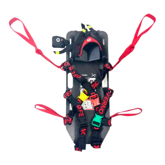
5 - XT MILITARY EXTRICATION DEVICE 5.1.1 Description and intended use 5.1.3 Reporting accidents The XT Military extrication device is a medical device In the event of a serious accident in relation to the device, designed for the immobilisation and extrication of trauma immediately contact Ferno S.r.l. - Page 41 XT Series Extrication Devices 5.2 - XT MILITARY components SNAP-HOOK TRIANGULAR HEAD LIFTING TAPE IMMOBILISER CHIN STRAP YELLOW CHEST RESTRAINT HEAD CUSHION - RED CHEST RESTRAINT AUXILIARY HANDLES (X 2) Slot numbering LIFTING AND CARRYING HANDLES (X 4) BLACK GROIN...
-
Page 42: Components (Xt Military Extrication Device)
COMPONENTS OF THE XT PRO EXTRICATION DEVICE Board with holes for restraint fastening ● WARNING QHI (Quick Head Immobilizer) ● Check that all the slots of the XT Military allow the Neoprene triangular head immobiliser ● tape and restraints to pass. Chin strap for QHI ●... - Page 43 55B) and the straps folded back on themselves and secured vital parameters with imminent danger to the life of with the supplied elastic and the chin strap stowed in the the casualty. bag provided. Figure 55A and 55B - XT MILITARY ready for use © Ferno s.r.l. Rel.05042024...
- Page 44 XT Series Extrication Devices WARNING For a better understanding of the procedure for the use of the XT Military extrication device, archive photos were used in which the XT PRO was applied in the outdated red QHI version, in order to make it more visible in the images with military camouflage.
- Page 45 (between the neck, helmet, bulletproof vest and Ferno XT) (Figure 62), and roll it up just enough to fill this space. (Figure 63). Figure 64 - Cushion ready to be positioned...
- Page 46 Then begin to gradually tighten the straps of the triangular head immobiliser (Figure 68) until the head is fully secured Figure 69 - Triangular head immobiliser applied to the XT MILITARY (Figure 69). Avoid over-tightening the straps or tightening them asymmetrically. WARNING...
- Page 47 At this point, the operator manually holding the person’s head can stop, as their head will be firmly secured to the XT MILITARY, and the operator will be free to perform the subsequent manoeuvres. Figure 73 - Extending the chest restraints...
- Page 48 Tightening will also secure the chest to the board of the XT MILITARY (Figures 77 and 78). Figure 76 - Tightening the chest restraints Figure 78 - Tightened chest restraints (Side view)
- Page 49 "saw-like" movement, as far as possible under the buttocks the colour coding of the restraints will be respected (Figure (Figure 83) with the help of your hands while pulling the 86). end between the legs (Figure 84). © Ferno s.r.l. Rel.05042024...
- Page 50 Therefore, check and, if necessary, re-tension the groin restraints before lifting. Once the groin restraints have also been tightened, the entire spine can be considered to be secured to the XT MILITARY (Figure 88) and the injured person can be extracted from the passenger compartment.
- Page 51 With a coordinated movement of the operators, the casualty is extracted from the passenger compartment by pulling the two pairs of auxiliary handles (Figure 93). Figure 94 - Intervention of the third operator to facilitate the exit of the lower limbs © Ferno s.r.l. Rel.05042024...
- Page 52 In this case, once the XT MILITARY has been secured to the casualty, the latter must be rotated by pulling the feet out of the vehicle.
-
Page 53: Xt Floating Extrication Device
In the event of a serious accident in relation to the device, designed for the immobilisation and extrication of trauma immediately contact Ferno S.r.l. and the competent authority and non-trauma patients, to ensure extreme manoeuvrability of the member State in which the user has its main office. - Page 54 YELLOW TRANSVERSE RESTRAINT SIGNAL LIGHT RED TRANSVERSE RESTRAINT Slot numbering BLACK RESTRAINT CONNECTING FLOATS LONGITUDINAL RETAINING STRIP BREAST FLOATS WARNING Check that all the slots of the board allow the lifting tape and restraints to pass. © Ferno s.r.l. Rel.05042024...
-
Page 55: Components (Xt Floating Extrication Device)
XT Series Extrication Devices 6.2.1 General technical specifications WARNING Ferno reserves the right to change the specifications without Untrained users may injure themselves, cause notice. For further details, please contact Ferno's Customer damage and/or physical harm. Allow only trained Service (page 2). -
Page 56: Xt Floating Extrication Device Assembly
(Figure 99B). Once the QHI has been correctly applied, it will be possible to use the Velcro to detach and attach the cushion during cleaning and disinfection or as required. Figure 99 - QHI application © Ferno s.r.l. Rel.05042024... -
Page 57: Assembling The Head-End Floats
Figures 101 and 102. It is important to carry out all three steps to ensure that the strap is securely fastened. Figure 101 - Steps for fastening on the head-end float Figure 102 - Fastening the central strap buckles © Ferno s.r.l. Rel.05042024... - Page 58 Repeat the operation described for the side fastening points, WARNING using slots 3 and 14. Always block excess tape, as shown in For correct assembly, the strap must be tensioned Figures 101, 102, 103A and 103B. as tightly as possible, respecting all the steps. © Ferno s.r.l. Rel.05042024...
-
Page 59: Qhi Chin Strap Assembly
Insert the end of the strap inside the buckle and complete the fastening as shown in Figures 105A, 105B and 105C. 105A 105B 105C Figure 105 - Chin strap fastening steps 6.3.4 Assembling the restraints Figure 106 - XT Floating restraint configuration before and after assembly © Ferno s.r.l. Rel.05042024... - Page 60 Alternatively, if you want to reproduce the “ready-to-use” configuration as in the XT Plus and Pro, you can choose to fit one of the two restraints (yellow or red) with the buckles inverted as shown in the drawing, so that, by attaching them together on the sides, the board remains free. © Ferno s.r.l. Rel.05042024...
-
Page 61: Assembling The Breast Floats And The Restraint With Black Buckle
(Figure 108B), then proceed to insert the restraint into the second sleeve starting from the centre of the float towards the outermost end as shown in Figure 108C. 108A 108B 108C Figure 108 - Assembling the retaining restraints on the breast floats © Ferno s.r.l. Rel.05042024... - Page 62 Then insert the buckles from the front (Figure 113), ensuring that the buckle locks the restraint firmly in place (Figure 114). Figure 112 - Positioning the breast floats to complete Figure 113 - Breast float metal buckle fastening the installation © Ferno s.r.l. Rel.05042024...
-
Page 63: Triangular Head Immobiliser Assembly
Then insert the strap into the plastic buckle adjacent to the 116D apex of the triangle and perform the complete fastening procedure as shown in Figure 116. Figure 116 - Fitting the upper strap to the head-end float © Ferno s.r.l. Rel.05042024... - Page 64 Fasten the side straps by passing them through the plastic slots of the transverse restraint following the same procedure as for the upper strap (Figure 117). 117A 117B 117C 117D Figure 117 - Fitting the side straps of the triangular head immobiliser Figure 118 - Triangular head immobiliser correctly installed © Ferno s.r.l. Rel.05042024...
-
Page 65: Signal Light Assembly
To facilitate switching on, the position of the light can be changed by rotating the relevant holder (Figure 121D and 121E). Figure 120 - Recommended signal light positioning 121A 121B 121C 121D 121E Figure 121 - Signal light application © Ferno s.r.l. Rel.05042024... -
Page 66: Assembling The Auxiliary Handles
To attach the red handles, follow the fixing procedure with cow hitch (Figure 122A and 122B). 122A 122B Figure 122 - Fixing the auxiliary handles © Ferno s.r.l. Rel.05042024... -
Page 67: Use Of The Xt Floating Extrication Device
Always assist the patient and never leave them alone during the operations with the device. WARNING Do not use XT Floating for extrication from vehicles, confined spaces and/or verticalisation. Use XT Floating only for water rescues. 123 - XT Floating storage © Ferno s.r.l. Rel.05042024... -
Page 68: Ready-To-Use" Configuration
Adopt the safety position with the patient in water, leaving the back free for the subsequent positioning of the XT Floating (Figure 125). Position the XT Floating under the patient's back (Figure 126). Figure 125 - Patient's safety position Figure 126 - XT Floating positioning © Ferno s.r.l. Rel.05042024... - Page 69 Figure 129 - Black restraint tensioning WARNING It is important that the black restraint is well stretched, so as to ensure a first immobilisation (although partial) and, above all, allow the patient Figure 131 - Red restraint fastening to float. © Ferno s.r.l. Rel.05042024...
- Page 70 Move the patient with the suitable carrying handles. The lower end of the breast floats must always be left free, without any constraints. 134B Figure 134 - Extraction from water via auxiliary handles Figure 133 - Using the auxiliary carrying handles © Ferno s.r.l. Rel.05042024...
-
Page 71: Maintenance
It is recommended that the XT undergo a complete product components. overhaul and certification by Ferno personnel once a year - Pay attention to the effects of moisture and frost, as these from the 10th year after purchase. -
Page 72: Xt Pro And Xt Military Maintenance
PERIODIC MAINTENANCE During each use: It is recommended that the XT undergo a complete product overhaul and certification by Ferno personnel once a year - Regularly check the proper functioning of the product and from the expiry of the warranty. -
Page 73: Xt Floating Maintenance
It is recommended that the XT undergo a complete product MAXIMUM useful life is considered to be equal to 10 overhaul and certification by Ferno personnel once a year years from its first use, so it must be replaced after this from the 10th year after purchase. -
Page 74: Disinfection
7. Clean by directly spraying the cleaning and disinfecting product then leave it to dry. Important 8. Re-fit the restraints only once they are dry. After disinfection/cleaning, ensure that the device and its components are completely dry before use. © Ferno s.r.l. Rel.05042024... -
Page 75: Inspection
2. Open the float zipper and extract the stuffing. Figure 135 - XT Plus, XT PRO and XT Military carry bag 3. Soak triangular head immobiliser, chin strap, padding and liners in a bowl with water and the sanitising detergent. Take care that the padding is completely submerged in the liquid (possibly by applying a weight). -
Page 76: Xt Plus - Inspection Sheet
The auxiliary straps and handles do not First used on show any damage or cuts. Inspection frequency The straps are correctly positioned, according to Ferno's instructions and Overhaul frequency colour code. The auxiliary straps and handles are firmly fastened to the board. -
Page 77: Xt Pro And Military - Inspection Sheet
The auxiliary straps and handles do not First used on show any damage or cuts. Inspection frequency The straps are correctly positioned, according to Ferno's instructions and Overhaul frequency colour code. The auxiliary straps and handles are firmly fastened to the board. -
Page 78: Xt Floating - Inspection Sheet
The auxiliary straps and handles do not First used on show any damage or cuts. Inspection frequency The straps are correctly positioned, according to Ferno's instructions and Overhaul frequency colour code. The auxiliary straps and handles are firmly fastened to the board. -
Page 79: 8- Accessories And Spare Parts
8 - ACCESSORIES AND SPARE PARTS Accessories WARNING Ferno offers various approved accessories for use with the The use of improper and unauthorised accessories XT extrication device. Always follow the directions in this may cause accidents, damage, and/or injury. Use instruction manual. -
Page 80: Spare Parts
XT Series Extrication Devices XT PLUS AND PRO STORAGE XT FLOATING STORAGE BAG CERVICAL COMPENSATION CUSHION Spare parts XT PLUS SPARE PARTS XT PRO AND XT MILITARY SPARE PARTS Description Part no. Description Part no. SET OF XT PLUS PRO KIT... -
Page 81: Spare Parts Assembly
Figure 137 - Assembling the reinforcing slots of the PRO KIT 9 - TECHNICAL SUPPORT Any corrective action carried out by non Ferno personnel will Ferno Technical Support automatically cancel any Civil Liability insurance and any Customer Service and Technical Support are important aspects of guarantee. -
Page 82: Warranty
10.2 Limitation of liability Ferno products are guaranteed to be free of manufacturing If a product is found to be defective, Ferno s.r.l. will defects for a period of 24 months, starting from the date repair, replace it, or refund the purchase price. Under no circumstances can Ferno s.r.l. -
Page 83: Training Record
XT Series Extrication Devices TRAINING RECORD Date Instructor Name Training Type © Ferno s.r.l. Rel.05042024... - Page 84 XT Series Extrication Devices TRAINING RECORD Date Instructor Name Training Type © Ferno s.r.l. Rel.05042024...
-
Page 85: Maintenance Record
XT Series Extrication Devices MAINTENANCE RECORD Date Type of Maintenance Maintenance Technician © Ferno s.r.l. Rel.05042024... - Page 86 XT Series Extrication Devices MAINTENANCE RECORD Date Type of Maintenance Maintenance Technician © Ferno s.r.l. Rel.05042024...
- Page 87 Product User and Maintenance Manual, required to operate the product safely, maintain its efficiency and reliability, and comply with the terms of the warranty. Ferno s.r.l. Ferno s.r.l., Pieve di Cento, Subsidiary of Savosa Via Benedetto Zallone 26 Via Tesserete, 67...
Need help?
Do you have a question about the XT MILITARY and is the answer not in the manual?
Questions and answers