
Related Manuals for Ferno iNLINE


Summary of Contents for Ferno iNLINE
- Page 1 Fastening System Users’ Manual March 2016 Pub. No. 234-3621-00 Read this Manual and Retain for Future Reference...
-
Page 2: Ferno Customer Relations
Limited Warranty Statement Queensland, Australia +617.3881.4999 The products sold by Ferno are covered by a limited warranty, which is printed on all Ferno invoices. The complete terms and conditions of the limited warranty, and the limitations of liability and disclaimers, are also available upon request by calling Ferno at 1.800.733.3766 or... -
Page 3: Table Of Contents
Release Button ___________________________________ 12 Training Record__________________________________________ 22 Safety Hook ______________________________________ 12 Fastening-Post Retainer ____________________________ 12 Maintenance Record _____________________________________ 23 Fastening-Post Lock _______________________________ 13 Integrated Charging System (ICS®) ___________________ 13 Floor Lock Indicator Window ________________________ 13 © Ferno-Washington, Inc. / March 2016 / 234-3621-00... -
Page 4: Safety Information
Ferno-Washington, Inc. products are designed for use only with Ferno- Ferno. manufactured fastening systems. Use of a Ferno cot/transport system with a non-Ferno fastening system is misuse of the Ferno product. The user assumes responsibility for the outcome of known, intentional misuse. -
Page 5: Symbol Glossary
Safety Information 1.6 Symbol Glossary The symbols defined at right are used on the fastening system and/ or in this’ manual. Ferno uses symbols recognized by the International Standards Organization (ISO), American National Standards Institute Read the Users’ Manual (ANSI) and the emergency medical services industry. -
Page 6: Compliance
1.8 Compliance Specifications/Standards SPECIFICATIONS AND STANDARDS Contact Information When properly installed and used with appropriate additional Ferno For information about AMD standards: products, the iN∫LINE™ fastening system meets or exceeds the Ambulance Manufacturer’s Division following global specifications and standards. Be aware: standards and National Truck Equipment Association specifications are updated periodically. -
Page 7: Responsibility Of User To Maintain A Safe Fastening System
WARNING Safe Fastening System Improper or inadequate installation can cause injury. The The Ferno® iN∫LINE™ fastening system is designed to securely hold installer should test the fastening system setup to meet a compatible Ferno product inside a ground-based ambulance. See or exceed all applicable guidelines. -
Page 8: Operator Focus
For a sample training record sheet, see ● "Training Record" on page 22. The Ferno Injury Free program from Ferno provides training on nutrition, exercise, management of stress and fatigue, ergonomics, and injury prevention, all from an emergency-medical services perspective. -
Page 9: Overview
Fastening System is a device designed to secure ® Improper use can cause injury. Use the fastening system a compatible Ferno ambulance cot or iN∫X® transport system inside a only for the purpose described in this manual. ground-based ambulance. See “Fastening System Compatibility” on An improper cot/transport system can cause injury. -
Page 10: General Specifications
Weight Frame Aluminum iN∫LINE-S 72 lb 32.7 kg Internal Components Steel General specifications are rounded. Metric conversions are calculated before rounding. Ferno Other Plastic reserves the right to change specifications without notice. © Ferno-Washington, Inc. / March 2016 / 234-3621-00... -
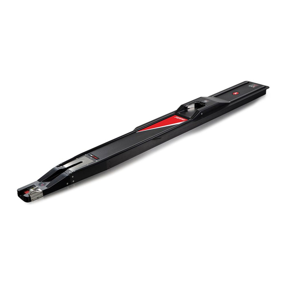
Page 11: Components
Floor Lock Screws Fastening Post Retainer Release Button Components Common to All Models The only variations between iN∫LINE models is Safety Hook the distance of the components from the nose/ Nose safety hook. © Ferno-Washington, Inc. / March 2016 / 234-3621-00... -
Page 12: Features
4 - FEATURES 4.1 Release Button The release button is located on the nose of the fastening system (Figure 1). Press the button to unlock the compatible Ferno product for unloading. See “Using the Fastening System” on page 14. Release Button Nose 4.2 Safety Hook... -
Page 13: Fastening-Post Lock
4.5 Integrated Charging System (ICS®) The Ferno® Integrated Charging System (ICS®) is located near the center of the fastening system (Figure 5). When a Ferno® iN∫X is locked in the fastening system and the ICS is connected and powered, the ICS will: ICS Charging Contacts disable powered operation of the iN∫X... -
Page 14: Using The Fastening System
Refer to the users' manual for loading and unloading instructions specific to your product. For additional manuals, contact Ferno. See “Ferno Customer Relations” on page 2. For a list of compatible Ferno products, see “Compatible Ferno Products” on page 9. -
Page 15: Maintenance
Wipe all surfaces with disinfectant. Follow the disinfectant Important manufacturer’s instructions for application method and contact time. Ferno recommends you inspect the fastening system for damage as Disinfectants and cleaners containing bleach, phenolics, or you disinfect. iodines can cause damage. Do not use products containing these chemicals. -
Page 16: Lubricating The Fastening System
● PRESSURE-WASHING THE FASTENING SYSTEM fastening system has been removed from the floor. Set the nozzle pressure at or below 3000 psi (20,684 kPa). Ferno DO NOT: Spray water into the ICS port. ● recommends you use a nozzle with a wide angle of spray (25° or 40°). -
Page 17: Removing The Fastening System From The Floor For Cleaning
Nose Screw (2) and Washer (2) M4 Wrench Upper Fastener ICS Cable Floor Connector Floor Lock Indicator Window Locator Pin (2) Set Screw Insert M6 Wrench Safety Hook Locator Pin (2) Fastening Bolt M6 Wrench © Ferno-Washington, Inc. / March 2016 / 234-3621-00... -
Page 18: Attaching The Fastening System To The Ambulance Floor
The fastening system should be in contact with the floor. Safety Hook Locator Pin (2) Upper Fastener ICS Cable Floor Connector Receiving Plate (3) Floor Post (3) ICS Cable Mounting Rail Floor Post (3) © Ferno-Washington, Inc. / March 2016 / 234-3621-00... - Page 19 10. Use and M4 Allen wrench to attach the two nose screws (Figure 19). Tighten until snug. Do not overtighten. Fastening Bolt M6 Wrench Nose Screw (2) and Washer (2) M4 Wrench © Ferno-Washington, Inc. / March 2016 / 234-3621-00...
-
Page 20: Parts And Service, Accessories
+617.3881.4999 +617.3881.1125 Internet http://www.ferno.com.au/ 7.3 United Kingdom/EU Representative In the European Union or in the United Kingdom, contact Ferno to order parts or for professional repairs. Ferno (UK) Limited Stubs Beck Lane, Cleckheaton West Yorkshire BD19 4TZ, England, United Kingdom Telephone +44 (0) 1274.851999... -
Page 21: Notes
NOTES © Ferno-Washington, Inc. / March 2016 / 234-3621-00... -
Page 22: Training Record
Training Record TRAINING RECORD Training Method Trainer Date Printed Name Signature Read Video/ Initials Hands-On Manual Online © Ferno-Washington, Inc. / March 2016 / 234-3621-00... -
Page 23: Maintenance Record
Maintenance Record MAINTENANCE RECORD Date Maintenance Performed © Ferno-Washington, Inc. / March 2016 / 234-3621-00... - Page 24 © Ferno-Washington, Inc. / March 2016 / 234-3621-00...
Need help?
Do you have a question about the iNLINE and is the answer not in the manual?
Questions and answers