Advertisement
Quick Links
Installation Instructions
Model:
Description:
Part Number:
Assembly Time:
Before you begin, read through these instructions and check that
all parts are present. Always disconnect negative battery terminal
prior to installation. Please note that MB Quart cannot assume any
responsibility for damage resulting from incorrect installation.
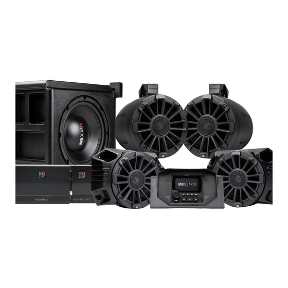
No.
1
GMR-LED w/Housing (MBQRG-RAD-1) (MBQRG-STG5-1 0nly)
2
6.5" Dash Speakers (MBQRG-FPOD-1)
3
10" Subwoofer w/Enclosure (MBQRG-SUB-1)
4
6.5" Rear Pod Speakers (MBQRG-RPOD-1)
5
MBQRG-ACC-1
6
NA2-400.1 Amplifier
7
NA2-400.2RC Amplifier
1
Bojo Tool
2
Panel Clip Pliers
3
1/8" Drill Bit
4
Drill
5
T25 Torx Bit
7
10mm Socket
8
Rachet
Polaris Ranger
Stage 5 Install
MBQRG-STG5-1 & MBQRG-STG5-RC-1
180 Min (3-Hours)
Parts List
Component Name
Tools Required
Page 1 of 26
Parts List
Qty
1
2
1
2
1
1
1
Advertisement

Related Manuals for MB QUART MBQRG-STG5-1


Summary of Contents for MB QUART MBQRG-STG5-1
- Page 1 Assembly Time: Before you begin, read through these instructions and check that all parts are present. Always disconnect negative battery terminal prior to installation. Please note that MB Quart cannot assume any responsibility for damage resulting from incorrect installation. Parts List...
-
Page 2: Dash Disassembly
Dash Disassembly ● Remove hood by turning two latches ● Remove two push pins from center cup holder ● Remove two push pins from instrument cluster. Remove and disconnect connector on back Page 2 of 26... - Page 3 Dash Disassembly ● Open upper glove box and then remove four T20 Torx screws. Then lift assembly out of vehicle ● Remove three push pins on the passenger side dash ● Remove three push pins on the driver side dash Page 3 of 26...
- Page 4 Dash Disassembly ● Remove six push pins from the front of the dash ● Lift up on the dash and remove from vehicle Page 4 of 26...
-
Page 5: Harness Installation
Harness Installation ● Remove four push pins from the passenger side center console ● Remove five push pins from the driver side center console ● Lift center console upward starting at cupholder and remove from vehicle Page 5 of 26... - Page 6 Harness Installation ● Install front speaker wires placing the four pin connector in the middle of the dash and extending the white wires to the driver side of the dash and the gray wires to the passenger side of the dash ●...
- Page 7 Harness Installation ● On the radio harness pass the power connection through the grommet toward the front of the vehicle and plug into an open port on the pulse junction block ● Pass the amplifier power harness from the front of the vehicle into the cab through the grommet ●...
- Page 8 Harness Installation ● Connect the blue wire from the amplifier harness to the blue wire on the radio harness ● Route the rear speakers and subwoofer extension harness from the middle of the dash out the grommet toward the front of the vehicle ●...
- Page 9 Harness Installation ● Pass the wiring around any moving parts and down the frame toward the center console and secure in place with zip ties ● Run along air intake securing with zip ties to the power bus bar harness ●...
- Page 10 Harness Installation ● Drill 1.25” hole and pass subwoofer connection through hole and place grommet ● If four-seat vehicle, connect extension harness to route rear speaker wires to the back of the vehicle if installing rear pods jump to that section ●...
- Page 11 Dash Speaker Installation ● Drill four 1/8” holes at the noted dimples on driver side ● Connect the speaker wires to the speaker and then install the speaker and grill assembly with four high-low torx screws and washers using a T25 Torx bit ●...
- Page 12 Amplifier & Amplifier Plate Installation ● Install the NA2-400.2RC and NA2-400.1 amplifier as pictured with four M4 Philips screws, washers, and lock nuts ● Adjust the NA2-400.2RC amplifier gain as pictured Note Turn Gain all to the last “L” on Level ●...
- Page 13 Amplifier & Amplifier Plate Installation ● Passing amplifier plate between dash supports and mounted below dash supports ● Raise the plate and install two 10-32 x ¾” bolt and washer into amplifier plate ● Plug in the amplifier harness connectors to the amplifiers Page 13 of 26...
- Page 14 Amplifier & Amplifier Plate Installation ● Connect the subwoofer extension harness to the NA2-400.1 amplifier harness ● Connect the speaker y-harness to the front and rear speaker harnesses ● Connect into the NA2-400.2 amplifier Page 14 of 26...
- Page 15 Amplifier & Amplfier Plate Installation ● Connect the two RCAs to each of the amplifier (the red connector goes into the RCA input closest to the amplifier’s mounting feet) Page 15 of 26...
-
Page 16: Subwoofer Installation
Subwoofer Installation ● Drill three 1/8” holes at marked indents in floor (only drill deep enough to get through first layer of material) ● Place subwoofer enclosure under passenger seat and secure with three high-low T25 Torx screws and washers Note Use two picks to align enclosure with holes in vehicle and also use... - Page 17 Rear Speaker Pod Installation ● Attach the left and right harness to bullet connectors in the center console ● Mark a drill location (7.5” from middle seat belt bracket and 2” down from rear lip) Page 17 of 26...
- Page 18 Rear Speaker Pod Installation ● Drill 1/2” hole and then pass rear speaker wire from battery compartment out to inside of passenger cabin ● Pass speaker wires through grommet and insert grommet into the drilled hole ● Place two adhesive channels on passenger side under the seat on the metal frame Page 18 of 26...
- Page 19 Rear Speaker Pod Installation ● Route passenger side violet speakers wire-in channels toward passenger door, then route upward toward the ROPS (avoiding any moving objects), secure, and attach one adhesive channel on ROPS ● Place one adhesive channel on driver side under seat on frame ●...
- Page 20 Rear Speaker Pod Installation ● Position bracket on the ROPS and secure with four M6 bolts with a 5mm Allen wrench and 13mm socket (same process on passenger and driver side) Note Inside bracket should have grove facing toward center of vehicle ●...
- Page 21 Assembly & Dash Radio Install ● Place top of dash in vehicle ● Install three push pins on driver side of dash ● Connect harness and place the instrument panel in location and then insert two push pins Page 21 of 26...
- Page 22 Assembly & Dash Radio Install ● Install three push pins on passenger side dash ● Install upper glove box with four T20 Torx screws ● Install six push pins on the front side of the dash Page 22 of 26...
- Page 23 Assembly & Dash Radio Install ● Connect the radio harness, RCAs and USB/AUX (PSAP-18) harness to the radio NOTE If you have a Ride Command you will connect the RC1-2RCA-F to the “AMP2” (which will supply signal to the NA2-400.2RC) Connect another RC1-2RCA-F to the “AMP3”...
- Page 24 Assembly ● Insert four push pins on passenger side console ● Place five push pins on driver side center console ● Place battery cover into place RECONNECT NEGATIVE BATTERY TERMINAL Page 24 of 26...
- Page 25 Assembly ● Turn vehicle and radio on and enjoy the music Page 25 of 26...
- Page 26 The Bluetooth ® word mark and logos are registered trademarks owned by the Bluetooth SIG, Inc. and any use such marks by MB Quart is under license. All product names, logos, and brands are property of their respective owners. All company, product and service names used in this literature are for identification purposes only.
Need help?
Do you have a question about the MBQRG-STG5-1 and is the answer not in the manual?
Questions and answers