
Related Manuals for MB QUART MBQR-POD-2


Summary of Contents for MB QUART MBQR-POD-2
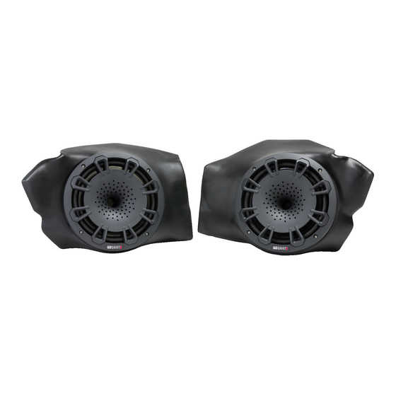
- Page 1 Installation Manual MBQR-POD-2 8-Inch 2-Way Compression Horn Speakers in Kick Panel Enclosures for Polaris Vehicles ® ®...
-
Page 2: Support Tab
INSTALL & SUPPORT tab. WHAT’S INCLUDED The RZR ® MBQR-POD-2 kick panels with 8-inch speakers ship in one box and these work equally well with either non-Ride Command ® vehicles or those equipped with the Ride Command ®... -
Page 3: Installation Time
You may also own more specialized tools to complete the installation. Please share the pictures of your installation on MB Quart social media channels to help others. In addition to the tools listed, have music ready for the INITIAL TESTING step. MB Quart recommends: ● USB thumb drive with music pre-loaded ●... - Page 4 MBQR-RAD-2 digital media source unit AUDIO SYSTEM ACCESSORIES FOR YOUR Polaris® RZR® MB Quart offers audio system accessories to further personalize your vehicle. You can find more information at www.MBQuart.com. SR1-120RGB LED RING LIGHT The optional 8-inch SR1-120RGB LED ring light features 16...
- Page 5 DASH AREA DISASSEMBLY 2013-2018 (Non-Turbo S) RZR Please note, separate disassembly instructions for the 2018.5 Turbo S and 2019+ RZR models are found on pages 7-9 in this manual. STEP 1 – REMOVE CENTER HOOD Figure 5-1 Start with removing the hood as shown in Figure 5-1. Twist the tabs at the upper left and right corners.
- Page 6 DASH AREA DISASSEMBLY 2013-2018 (Non-Turbo S) RZR - Continued STEP 5 – REMOVE DASH FASCIA CENTER HARDWARE Remove (4) Torx screws from the front of the dash through the openings shown in Figure 5-6. The first set of Torx screws will come out allowing access to the second (upper) set further back in the dash. Next, pull the only the center of the dash loose as shown in Figure 5-7.
- Page 7 DASH AREA DISASSEMBLY 2018.5 Turbo S & 2019+ RZR (RIDE COMMAND) Please note, separate disassembly instructions for the 2013-2018 RZR models are found on pages 5-6 in this manual. STEP 1 – REMOVE CENTER HOOD Figure 7-1 Remove the center of the hood area as shown in Figure 7-1.
- Page 8 DASH AREA DISASSEMBLY 2018.5 Turbo S & 2019+ RZR - Continued ® STEP 4 – REMOVE DYNAMIX ECU BRACKET OR POCKET SCREW If no Ride Command, Dynamix ECU or OEM installed amplifier are present, proceed to removing lower pocket. If you have the Dynamix ECU or OEM installed amplifier, remove (4) 10mm bolts holding the bracket as shown in Figure 7-4a.
- Page 9 DASH AREA DISASSEMBLY 2018.5 Turbo S & 2019+ RZR - Continued STEP 7 – PREPARE FINAL ELECTRONICS FOR DASH REMOVAL Gently remove the plastic nut holding the ignition switch to the dash as shown in Figure 7-7a. Next, disconnect wires from back of switches as shown in Figure 7-7b. Take note of plug color and switch location for reassembly purposes.
- Page 10 MOUNTING THE KICK PANEL SPEAKERS Through hundreds of installations, we’ve found once mounting holes are drilled, it’s best to start with the driver’s side kick panel and then move on to the passenger’s side kick panel to complete the mounting and wiring of the kick panels.
- Page 11 MOUNTING THE KICK PANEL SPEAKERS (Continued) STEP 6 – PLACE PASSENGER SIDE KICK PANEL Place passenger side kick panel pod in its location as shown in Figure 14-5. Ensure the positioning lines up with the holes you’ve drilled. STEP 7 – PUSH OUTER BOLTS THROUGH FENDER AND MOUNT DRIVER’S SIDE KICK PANEL With the included hardware push (1) bolt and (1) washer through the inner passenger side fender well into the threaded insert of the...
-
Page 12: Initial Testing
INITIAL TESTING This step is to confirm that everything is working before you put the vehicle back together. STEP 1 – RECONNECT THE BATTERY Figure 19-1 With the kick panel speakers wired to your amplifier, you can now reconnect the negative terminal of the negative battery cable as indicated in Figure 19-1. -
Page 13: Final Inspection
VEHICLE REASSEMBLY Follow along the dual amplifier audio harness and zip-tie the harness to the vehicle to assure it doesn’t come loose during rides. Do not zip-tie the harness to any heat or moisture sources. Here is an important checklist so you do not forget anything: 2013-2018 RZR Models ●... - Page 14 This is a complete wiring harness layout diagram of a RZR Stage 5 system. Your kick panels are only one part of the whole audio system package possible. Part#MBQR-POD-2 Shown To view all the RZR-Tuned Audio System Options, visit MBQuart.com...
- Page 15 NOTES Use this section to record serial numbers of each product, final gain and crossover settings of amplifiers or any other wiring or installation-related details that will be helpful if you need to add on to the system or troubleshoot any unforeseen issues.
- Page 16 The Bluetooth ® word mark and logos are registered trademarks owned by the Bluetooth SIG, Inc. and any use such marks by MB Quart is under license. All product names, logos, and brands are property of their respective owners. All company, product and service names used in this literature are for identification purposes only.
Need help?
Do you have a question about the MBQR-POD-2 and is the answer not in the manual?
Questions and answers