Advertisement
Quick Links
Installation Instructions
Model:
Description:
Part Number:
Assembly Time:
Before you begin, read through these instructions and check that
all parts are present. Always disconnect negative battery terminal,
prior to installation. Please note that MB Quart cannot assume any
responsibility for damage resulting from incorrect installation.
No.
1
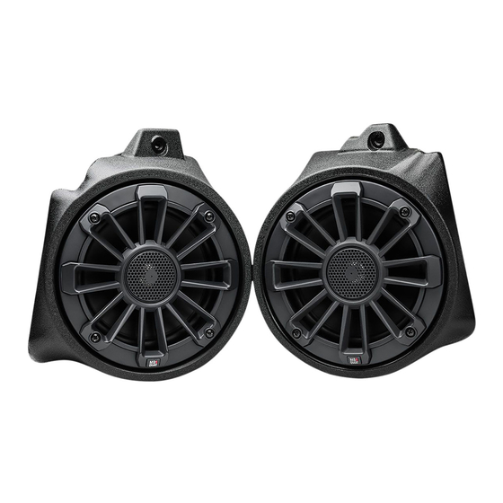
6.5" Rear Pod Speakers (MBQT-FPOD-1)
2
NA2-400.2 Amplifier
1
Bojo Tool
2
Panel Clip Pliers
3
10mm open box wrench
4
10mm and 12mm socket
5
½" socket
6
Rachet
7
Small flat head screwdriver
8
Phillips screwdriver
9
3mm and 5mm Allen Wrench
10
¼" and ½" drill bit or stepper bit
11
1" hole saw
12
Drill
13
Rotary tool similar to a Dremel
14
Heat Gun or Lighter
15
Crimper
Honda Talon
Front Speaker Pod Install
MBQT-FPOD-1
150 Mins (2.5-Hours)
Parts List
Component Name
Tools Required
Page 1 of 15
Qty
2
1
Advertisement

Related Manuals for MB QUART MBQT-FPOD-1


Summary of Contents for MB QUART MBQT-FPOD-1
- Page 1 Assembly Time: Before you begin, read through these instructions and check that all parts are present. Always disconnect negative battery terminal, prior to installation. Please note that MB Quart cannot assume any responsibility for damage resulting from incorrect installation. Parts List Component Name 6.5”...
- Page 2 Disassembly ● Remove hood by turning two latches ● Remove four 10mm bolts, four push pins and five 5mm allen bolts to remove top of dash ● Remove half mud guard with six push pins Page 2 of 15...
- Page 3 Disassembly ● Lift up the bottom half of the steering column rubber boot ● Remove the two push pins behind the rubber boot ● Remove the two push pins on the bottom of steering column cover Page 3 of 15...
- Page 4 Disassembly ● Remove the bottom steering wheel cover ● Remove one 5mm allen bolt and one push pin from the drivers kick area ● Remove two 5mm allen bolts from behind glove box door Page 4 of 15...
- Page 5 Disassembly ● Remove one push pin in the back of the glove box ● Remove three push pins from below the glove box ● Remove glove box Page 5 of 15...
- Page 6 Disassembly ● Remove one 5 mm allen bolt and one push pin from passenger kick area Page 6 of 15...
- Page 7 Front Speaker Pod Installation ● Drill a ½” hole, 5/8” down from the edge, and 2 ¼” over (Control the depth of bit to not go to deep) ● Pass the wire from the driver side pod through the hole you drilled ●...
- Page 8 Front Speaker Pod Installation ● Install the M6 x 40mm bolt and washer through the enclosure into the factory bolt location ● Tighten the 5/16” bolt in the fender area ● Repeat previous steps on passenger side Page 8 of 15...
-
Page 9: Amplifier Adjustment
Amplifier Adjustment ● Adjust the NA2-400.2 amplifiers gain and crossover settings as pictured NOTE Gains all to the last “L” on Level HPF to 100Hz going just past “P” on LP LPF is turned all the way down X-Over to HP Page 9 of 15... -
Page 10: Wiring Installation
Wiring Installation ● Connect the speaker harness to the NA2-400.2 amplifier and route the driver and passenger speaker leads to the appropriate kick area ● Connect bullets of amplifier harness with respective front kick pods ● If you don’t already have a buss bar installed you can connect to factory wiring (we highly recommend a buss bar kit) - Page 11 Reassembly ● Install glove box ● Install three push pins from below the glove box ● Install one push pin in the back of the glove box Page 11 of 15...
- Page 12 Reassembly ● Install two 5mm allen bolts from behind glove box door ● Install the bottom steering wheel cover ● Install the two push pins on the bottom of steering column cover Page 12 of 15...
- Page 13 Reassembly ● Install the two push pins behind the rubber boot ● Replace the bottom half of the steering column rubber boot ● Install half mud guard with six push pins Page 13 of 15...
- Page 14 Reassembly ● Install four 10mm bolts, four push pins, and five 5mm allen bolts to remove top of dash ● Install hood by turning two latches Page 14 of 15...
- Page 15 The Bluetooth ® word mark and logos are registered trademarks owned by the Bluetooth SIG, Inc. and any use such marks by MB Quart is under license. All product names, logos, and brands are property of their respective owners. All company, product and service names used in this literature are for identification purposes only.
Need help?
Do you have a question about the MBQT-FPOD-1 and is the answer not in the manual?
Questions and answers