Advertisement
Quick Links
BEGA
Installation and Technical Information
Tools Required:
• T15 torx head screwdriver
• T20 torx head screwdriver
• Flat head screwdriver
Overview:
LED Watts:
20W
System Watts:
27W
Controllability:
0-10V, TRIAC, and ELV dimmable
Weight:
7.3 lbs.
Protection Class: IP65
Notice to Installer:
1. See page 3 for specific product safety warnings.
2. BEGA luminaires may be damaged if connected to conduit systems containing water - Article
300-5G of National Electric Code requires that "Conduits or raceways through which moisture
may contact energized live parts shall be sealed or plugged at either or both ends."
3. Suitable for installation in hollow wall construction or poured concrete construction.
4. Installation housing provided with (6) 1/2" NPT threaded conduit holes.
5. Installation housing must be installed so that the front face is flush with the finished wall.
6. Suitable for wall applications only. (No ceiling or in-grade applications).
Warning: A silicone-based sealant MUST be used between the faceplate of the installed
fixture and the exposed surface of the back box. Failure to do so could result in water entry
into back box and fixture failure.
BB24573 installation in hollow (stud) wall or masonry construction:
1. Install (2) slotted mounting brackets provided as shown in Figure 1, using the (4) self-tapping
T20 torx head screws provided with the included kit (Kit #93).
2. Adjust the brackets so that the front face of the installation housing will be flush with the finished
wall surface after installation, Figures 2a / 2b.
3. Secure the mounting brackets to wood or metal horizontal blocking using hardware (by others)
as shown in Figure 2a OR to masonry unit using hardware (by others) as shown in Figure 2b.
4. Remove plastic insert.
5. Connect conduit to installation housing and pull wires for electrical connections to be made later.
6. Replace plastic insert and finish wall.
BB24573 installation in poured concrete construction:
1. Remove plastic insert.
2. Install (4) threaded M4 rods into the installation housing and hand tighten until fully secure.
3. Connect conduit to installation housing and pull wires for electrical connections to be made later.
4. Replace plastic insert, rods will fit through holes in plastic insert.
5. Attach the installation housing to concrete forms by using (8) wing nuts provided, Figure 3.
Ensure that the front face of the installation housing will be flush with the finished surface.
6. Pour concrete. Do not pump or drop concrete directly on top of the installation housing. Doing
so could deform or damage the installation housing.
7. After concrete has cured, remove wing nuts from threaded rods before removing the forms.
24573 luminaire installation:
1. Remove plastic insert and debris from installation housing.
2. Make wiring connection:
MAIN VOLTAGE SUPPLY WIRE TO BLACK DRIVER WIRE
NEUTRAL (COMMON) SUPPLY WIRE TO WHITE DRIVER WIRE
GREEN GROUND WIRE TO GREEN DRIVER WIRE/LUMINAIRE HOUSING
Dimming (if applicable):
DIMMING CONTROL WIRE (+) TO POSITIVE DRIVER DIM CONTROL WIRE
DIMMING CONTROL WIRE (-) TO NEGATIVE DRIVER DIM CONTROL WIRE
3. Insert luminaire into installation housing and secure into place by evenly tightening the (4) T15
torx head screws on the front of the luminaire to engage the clamping system, Figure 4. Before
tightening completely, apply a silicone-based sealant as outlined below:
Apply a silicone-based sealant between the faceplate of the installed fixture and the
exposed surface of the back box to prevent water from entering the back box. At a
minimum, use silicone on the top and side edges of the fixture.
Accessories
Please refer to the appropriate accessory installation
sheet for further instruction when applicable.
BEGA 1000 Bega Way, Carpinteria, CA 93013 (805)684-0533 © copyright BEGA 2024
Due to the dynamic nature of lighting products and the associated technologies, luminaire data on this sheet is subject to change at the discretion of BEGA North America. For the most current technical data, please refer to bega-us.com
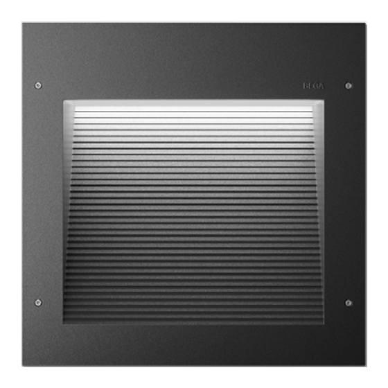
Recessed wall luminaire - shielded
Dimensions
A: 11-3/4"
B: 11-3/4"
C: 5-1/4"
Figure 1: Included brackets
Stud bracket
Figure 2a: Hollow (stud) wall
Figure 3: Poured concrete
Figure 4: Installation
Maintenance:
Clean regularly with solvent-free cleaner
removing dirt and debris. Do not use high
pressure cleaners.
Replacement Parts
See label inside of fixture for LED replacement
part number.
Consult factory for all other replacement
components.
24 573
Masonry bracket
Figure 2b: Masonry wall
T15 Screws
Updated: 03/21/24
24 573
1 of 3
Advertisement

Related Manuals for BEGA 24 573


Summary of Contents for BEGA 24 573
- Page 1 1 of 3 Due to the dynamic nature of lighting products and the associated technologies, luminaire data on this sheet is subject to change at the discretion of BEGA North America. For the most current technical data, please refer to bega-us.com...
- Page 2 2 of 3 Due to the dynamic nature of lighting products and the associated technologies, luminaire data on this sheet is subject to change at the discretion of BEGA North America. For the most current technical data, please refer to bega-us.com...
- Page 3 3 of 3 Due to the dynamic nature of lighting products and the associated technologies, luminaire data on this sheet is subject to change at the discretion of BEGA North America. For the most current technical data, please refer to bega-us.com...
Need help?
Do you have a question about the 24 573 and is the answer not in the manual?
Questions and answers