Advertisement
BEGA
Installation and Technical Information
Tools Required:
2mm hex key
11/32" Nut driver
Phillips medium screwdriver
Small Flathead screwdriver
Protection Class: IP64
Weight: 1.0 lb.
Notice to Installer for 33 539:
1. See page 2 for specific product safety warnings.
2. Mounts directly to a standard single-gang recessed wiring box (by others) using
adaptor plate (supplied).
3. In conformance with UL Standard 1598, a silicone based sealant must be used
between luminaire and supporting wall.
IMPORTANT:
SILICONE RTV MUST BE APPLIED ON BOTH SIDES OF THE ADAPTOR PLATE
TO ENSURE AGAINST WATER INTRUSION.
33 539 - Installation:
1. Using a small flathead screwdriver, loosen (2) set screws under luminaire and
remove outer casting with lens. [Figure 1]
2. Feed luminaire wires through luminaire base and adaptor plate wireway hole.
3. Make supply wiring and luminaire wiring connections in the wiring box:
MAIN VOLTAGE SUPPLY WIRE TO BLACK LUMINAIRE WIRE
NEUTRAL (COMMON) SUPPLY WIRE TO WHITE LUMINAIRE WIRE
4. Place a bead of silicone RTV around the outer edge of the back side of the
adaptor plate that will come in contact with the finished wall
(exterior applications only).
5. Attach adaptor plate to single-gang wiring box using (2) wiring box screws.
6. Apply silicone RTV to outside edge of luminaire base and mount luminaire base
to adaptor plate using (2) screws (provided).
IMPORTANT: Note position of orientation arrow on luminaire base and install
accordingly.
7. Replace outer casting and tighten (2) set screws, making sure the gasket is
seated properly.
Relamping/Maintenance
Loosen (2) 2mm set screws under luminaire and
remove outer casting with lens. Clean luminaire and
lens using only solvent-free cleansers. Replace lens
and outer casing, making sure that the gasket is
seated properly.
Lamp:
3.2W LED
In the interest of product improvement, BEGA reserves the right to make technical changes without notice.
BEGA 1000 Bega Way, Carpinteria, CA 93013 (805)684-0533 Fax (805)566-9474 www.bega-us.com © Copyright BEGA-US 2019
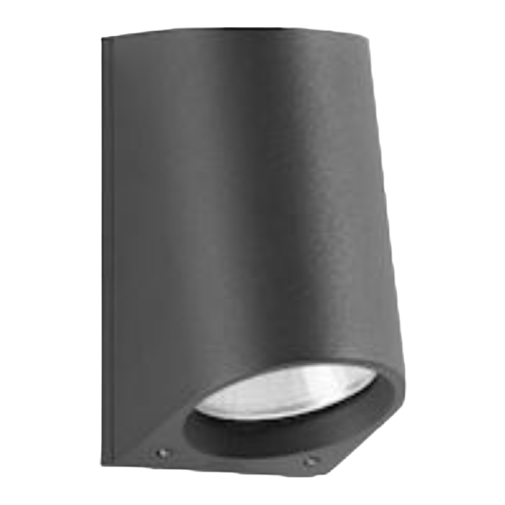
Surface wall with shielded light source
Figure 1:
Figure 2:
Adapter Plate
Accessories
Please refer to the appropriate
accessory installation sheet for
further instruction when applicable.
Dimensions
A:
3 "
B:
5-1/8 "
C:
3 1/4 "
Luminaire Base
Replacement Parts
Description
Lens
Lens gasket
Driver (120-277V) (X1)
LED module (3000K) (X1)
LED module (4000K) (X1)
33 539
Set Screws
Wiring Box
Part No
140787
831223
75911
LED-0684/830
LED-0684/830
33 539
07/15/2019
1 of 2
Advertisement
Table of Contents

Subscribe to Our Youtube Channel
Related Manuals for BEGA 33 539


Summary of Contents for BEGA 33 539
- Page 1 3.2W LED LED module (4000K) (X1) LED-0684/830 In the interest of product improvement, BEGA reserves the right to make technical changes without notice. 33 539 BEGA 1000 Bega Way, Carpinteria, CA 93013 (805)684-0533 Fax (805)566-9474 www.bega-us.com © Copyright BEGA-US 2019...
- Page 2 CONVIENT AUX EMPLACEMENTS MOUILLÉS. LES FILS D’ALIMENTATION 90°C MIN. In the interest of product improvement, BEGA reserves the right to make technical changes without notice. 33 539 BEGA 1000 Bega Way, Carpinteria, CA 93013 (805)684-0533 Fax (805)566-9474 www.bega-us.com © Copyright BEGA-US 2019...
Need help?
Do you have a question about the 33 539 and is the answer not in the manual?
Questions and answers