Advertisement
Available languages
Available languages
Quick Links
Installation Instructions
L[X]M[X]M4[X]-6-60-[X]14-72
SW3-1108 - v1
1. Introduction
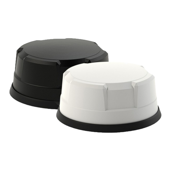
The L[X]M[X]M4[X]-6-60-[X]14-72 MiMo antenna is designed as a dual 4x4 solution for routers with appropriate port mapping. The robust low profile hous-
ing contains 4x 4G LTE / 5G NR elements covering 617-960/1427-6000MHz (low medium and high (LMH) bands) and 2x or 4x 4G LTE / 5G NR elements
covering 1710-6000MHz (medium and high (MH) bands) . Versions of the product are available with up to 2x WiFi elements supporting WiFi 6e 2.4/5.150-
7.125GHz and optional L1 only or L1/L5 GPS/GNSS. The antenna is suitable for fitment to panels up to 4mm (0.15") thick.
Electrical Safety Note
LGM[X]M4[X]-6-60-[X]14-72
M[X]M4[X]-6-60-[X]14-72
LG5
The supply to these devices must be provided with over current protection of 1A maximum.
2. Mounting requirements and selecting location
The L[X]M[X]M4[X]-6-60-[X]14-72 range can be mounted on a conductive or non-conductive panel. Select a mounting location, checking for panel
curvature to ensure that the antenna base will have a flat mounting surface if possible.
Ensure that there is adequate under panel clearance and that there are no obstructions under the panel. Measure to check for central position if
applicable. For optimal performance the antenna should, if possible, be mounted at least 300mm (1ft) away from other conductive objects on the mounting
panel.
Important Note Regarding Sealing
It is important that the periphery of the antenna is sealed and that no moisture is allowed to penetrate under the antenna boot.
To ensure that the antenna base is effectively sealed against the mounting surface, care must be taken regarding curvature of the mounting panel.
It is highly recommended that the antenna is installed on a clean, flat and level surface. After installation, the compression of the rubber boot
against the mounting panel should be checked - If necessary, a small bead of neutral cure silicone sealant can be applied around the edge of the
mounting boot.
3. Prepare and drill hole
Mask panel area around hole position to protect fi nish. Drill a pilot hole, and then increase to 19mm (3/4"), ensuring that drill/ cutter bit does not
contact any parts under the panel. Clean area around the hole, carefully removing all swarf.
4. Fitting the antenna
Note:It is recommended that the installation is carried out when the temperature is greater than 50°F (10°C) as the ideal temperature for the pad bonding
is 70°F (21°C) to 100°F (37°C).
Remove protective backing from underside of antenna, feed coaxial cables through panel. Position the antenna over the hole ensuring correct orientation
and stick to panel by applying firm, even, downward pressure. When fitting the nut, it is important to ensure that the cables are held centrally whilst the nut
is correctly started on the threads. The nut should fit freely by hand and only requires a final tighten by spanner to a recommended torque of 5Nm.
IMPORTANT: Do not exceed a torque of 5Nm (3.6ft/lbs) when tightening the securing nut.
contains an active L1 Band GPS/GNSS antenna. Rated voltage: 3-5VDC Rated current: <20mA maximum.
contains an active L1/L5 Band GPS/GNSS antenna. Rated voltage: 3-5VDC Rated current: <50mA maximum.
EN
Advertisement

Related Manuals for Panorama Antennas L M M4-6-60-14-72 Series


Summary of Contents for Panorama Antennas L M M4-6-60-14-72 Series
- Page 1 Installation Instructions L[X]M[X]M4[X]-6-60-[X]14-72 SW3-1108 - v1 1. Introduction The L[X]M[X]M4[X]-6-60-[X]14-72 MiMo antenna is designed as a dual 4x4 solution for routers with appropriate port mapping. The robust low profile hous- ing contains 4x 4G LTE / 5G NR elements covering 617-960/1427-6000MHz (low medium and high (LMH) bands) and 2x or 4x 4G LTE / 5G NR elements covering 1710-6000MHz (medium and high (MH) bands) .
- Page 2 5. Routing and terminating coaxial cable(s) The L[X]M[X]M4[X]-6-60-[X]14-72 includes two elememt types; those marked 4G/5G-A/B/C/D in yellow cover low, medium and high (LMH) bands 617- 960/1427-6000MHz an those marked Cell 1/2/3/4 in blue cover medium and high (MH) bands only 1710-6000MHz. The port mapping information for the router should be checked to ensure that the correct element type is connected to the correct port on the router.
-
Page 3: Instructions D'installation
Instructions d’installation L[X]M[X]M4[X]-6-60-[X]14-72 SW3-1108 - v1 1. Introduction L’antenne MiMo L[X]M[X]M4[X]-6-60-[X]14-72 est conçue comme une solution double 4x4 pour les routeurs avec un mappage de port approprié. Le boîtier robuste à profil bas contient 4 éléments 4G LTE / 5G NR couvrant 617-960/1427-6000 MHz (bandes basses, moyennes et élevées (LMH)) et 2 ou 4 éléments 4G LTE / 5G NR couvrant 1710-6000 MHz (bandes moyennes et élevées (LMH)) MH) bandes) . - Page 4 Lors du montage de l’écrou, il est important de s’assurer que les câbles sont maintenus au centre tandis que l’écrou est correctement engagé sur les file- tages. L’écrou doit s’ajuster librement à la main et ne nécessite qu’un serrage final avec une clé au couple recommandé de 5 Nm. IMPORTANT : Ne dépassez pas un couple de 5 Nm (3,6 pi/lbs) lors du serrage de l’écrou de fixation.
-
Page 5: Instrucciones De Instalación
Instrucciones de instalación L[X]M[X]M4[X]-6-60-[X]14-72 SW3-1108 - v1 1. Introducción La antena MiMo L[X]M[X]M4[X]-6-60-[X]14-72 está diseñada como una solución dual 4x4 para enrutadores con asignación de puertos adecuada. La robusta carcasa de perfil bajo contiene 4 elementos 4G LTE/5G NR que cubren 617-960/1427-6000 MHz (bandas baja, media y alta (LMH)) y 2 o 4 elementos 4G LTE/5G NR que cubren 1710-6000 MHz (media y alta ( MH) bandas). - Page 6 Al colocar la tuerca, es importante asegurarse de que los cables queden sujetos centralmente mientras la tuerca se inicia correctamente en las roscas. La tuerca debe encajar libremente con la mano y solo requiere un apriete final con una llave al par recomendado de 5 Nm. IMPORTANTE: No exceda un par de 5 Nm (3,6 pies/libras) al apretar la tuerca de seguridad.
- Page 7 Installationsanleitung L[X]M[X]M4[X]-6-60-[X]14-72 SW3-1108 - v1 1. Einführung Die L[X]M[X]M4[X]-6-60-[X]14-72 MiMo-Antenne ist als duale 4x4-Lösung für Router mit entsprechender Portzuordnung konzipiert. Das robuste Low-Pro- file-Gehäuse enthält 4x 4G LTE / 5G NR-Elemente, die 617–960/1427–6000 MHz (niedrige, mittlere und hohe (LMH) Bänder) abdecken, und 2x oder 4x 4G LTE/5G NR-Elemente, die 1710–6000 MHz (mittlere und hohe Bänder) abdecken.
- Page 8 Bei der Montage der Mutter ist darauf zu achten, dass die Kabel mittig gehalten werden, während die Mutter korrekt auf das Gewinde gesetzt wird. Die Mutter sollte von Hand gedreht werden und muss lediglich abschließend mit einem Schraubenschlüssel mit einem empfohlenen Drehmoment von 5 Nm festgezogen werden.
-
Page 9: Istruzioni Per L'installazione
Istruzioni per l’installazione L[X]M[X]M4[X]-6-60-[X]14-72 SW3-1108 - v1 1. introduzione L’antenna MiMo L[X]M[X]M4[X]-6-60-[X]14-72 è progettata come doppia soluzione 4x4 per router con mappatura delle porte adeguata. Il robusto alloggia- mento a basso profilo contiene 4 elementi 4G LTE / 5G NR che coprono 617-960/1427-6000 MHz (bande basse, medie e alte (LMH)) e 2 o 4 elementi 4G LTE / 5G NR che coprono 1710-6000 MHz (bande medie e alte ( bande MH). - Page 10 Quando si monta il dado, è importante assicurarsi che i cavi siano tenuti centralmente mentre il dado è correttamente avviato sulle filettature. Il dado dovrebbe adattarsi liberamente a mano e richiede solo un serraggio finale con una chiave ad una coppia consigliata di 5 Nm. IMPORTANTE: non superare una coppia di 5 Nm (3,6 piedi/libbre) quando si stringe il dado di fissaggio.
Need help?
Do you have a question about the L M M4-6-60-14-72 Series and is the answer not in the manual?
Questions and answers