Table of Contents
Advertisement
VISIT VIKINGPUMP.COM FOR PDF OF CURRENT TSM ISSUE & TO VIEW REPAIR VIDEOS
TECHNICAL SERVICE MANUAL: INSTALLATION, OPERATION & MAINTENANCE
TABLE OF CONTENTS
Model Number Chart ..................................................................1
Introduction ................................................................................1
Safety Information & Instructions ...............................................2
Special Information ....................................................................3
Rotation ..................................................................................3
Pressure Relief Valves ...........................................................3
Maintenance ...............................................................................3
Lubrication ..............................................................................3
End Clearance Adjustment ....................................................3
Cleaning Pump .......................................................................3
Storage ...................................................................................3
Suggested Repair Tools .........................................................3
Pump Disassembly ....................................................................5
Pump Assembly .........................................................................5
Pressure Relief Valve Instructions .............................................9
Disassembly ...........................................................................9
Assembly ................................................................................9
Pressure Adjustment ..............................................................9
Important Ordering Information ..............................................9
.....................................................10
General Installation Notes ........................................................10
Foundation ............................................................................... 11
Component & Unit Lifting Features ......................................... 11
Alignment .................................................................................13
Piping .......................................................................................13
Start Up ....................................................................................14
Troubleshooting .......................................................................15
Vacuum Gauge - Suction Port .............................................15
Pressure Gauge - Discharge Port ........................................15
Rapid Wear .............................................................................16
Preventative Maintenance .......................................................17
Do's & Don'ts ...........................................................................17
Installation ............................................................................17
Operation ..............................................................................17
Maintenance .........................................................................18
MOTOR SPEED PRODUCT LINE: CAST IRON
75 SERIES™, 475 SERIES™
SIZES: G, GG, H, HJ, HL
.................................5
.............................6
..................7
..............8
© 2019 Viking Pump, Inc. • Cedar Falls, IA
MODEL NUMBER CHART
LIP SEAL
G75
GG75
H75
HJ75
HL75
INTRODUCTION
The illustrations used in this manual are for identification
purposes only and cannot be used for ordering parts.
Obtain a parts list from your Viking Pump
Always give a complete name of part, part number and
material with the model number and serial number of pump
when ordering repair parts. The unmounted pump or pump
unit model number and serial number are on the nameplate.
This manual only applies to the pump models specified in the
"Model Number Chart" on page 1. Pump specifications and
recommendations are listed in the Catalog Sections, which
are available at vikingpump.com.
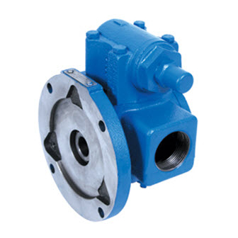
FIGURE 1: 475 SERIES™ UNMOUNTED PUMP
(HJ SIZE SHOWN)
FIGURE 2: 475 SERIES™ MOTOR MOUNTED PUMP
(HL SIZE SHOWN)
TSM
1445
Page
1 of 18
Issue
A
MECHANICAL SEAL
G475
GG475
H475
HJ475
HL475
representative.
®
Advertisement
Table of Contents

Subscribe to Our Youtube Channel
Related Manuals for Viking pump 75 Series


Summary of Contents for Viking pump 75 Series
-
Page 1: Table Of Contents
Pressure Gauge - Discharge Port ........15 Rapid Wear ................16 Preventative Maintenance ............17 Do’s & Don’ts ................17 FIGURE 2: 475 SERIES™ MOTOR MOUNTED PUMP (HL SIZE SHOWN) Installation ................17 Operation ................17 Maintenance .................18 © 2019 Viking Pump, Inc. • Cedar Falls, IA... -
Page 2: Safety Information & Instructions
BEFORE operating the pump, be sure that: information, refer to Appendix, General Installation Notes, • It is clean and free from debris. item 5 on Pressure Protection or contact your Viking Pump ® representative for Engineering Service Bulletin ESB-31. • All valves in the suction and discharge pipelines are fully opened. -
Page 3: Special Information
2. Allen wrenches (some mechanical seals and set collars) 3. Mechanical seal installation sleeve Relief Valve Adjusting 4. Brass or plastic bar Screw Cap 5. Arbor press Suction Discharge TSM 1445 | Issue A | Page 3 of 18 © 2019 Viking Pump, Inc. • Cedar Falls, IA... - Page 4 Rotor Capscrews for Head Contact your Authorized Viking Pump stocking distributor for available seal and rebuild kits ® FIGURE 5: EXPLODED VIEW - 75 SERIES™ & 475 SERIES™ (H, HJ, HL SIZE) Item Name Of Part Item Name Of Part...
-
Page 5: Pump Disassembly
The spring and rotary member of the mechanical seal. seal will come out with the rotor in these pumps. TSM 1445 | Issue A | Page 5 of 18 © 2019 Viking Pump, Inc. • Cedar Falls, IA... -
Page 6: Series™ Lip Seal Pumps (H, Hj, Hl Size)
“Table 2” on page 7 Check End Clearance gives the normal amount of gaskets used. Suckback Screw Motor Mounting Capscrew TSM 1445 | Issue A | Page 6 of 18 © 2019 Viking Pump, Inc. • Cedar Falls, IA... -
Page 7: 475 Series™ Mechanical Seal Pumps
G475, GG475 .010” - .015” valve or coverplate on the pump and fasten securely with 3 - .002” Plastic the four capscrews. TSM 1445 | Issue A | Page 7 of 18 © 2019 Viking Pump, Inc. • Cedar Falls, IA... -
Page 8: 475 Series™ Mechanical Seal Pumps
3. Install the rotor in the casing. 4. Install the idler. Put the idler with the bushing on the idler pin. TSM 1445 | Issue A | Page 8 of 18 © 2019 Viking Pump, Inc. • Cedar Falls, IA... -
Page 9: Pressure Relief Valve Instructions
Failure to follow above listed precautionary measures may result in serious injury or death. TSM 1445 | Issue A | Page 9 of 18 © 2019 Viking Pump, Inc. • Cedar Falls, IA... -
Page 10: Appendix (Formerly Tsm 000)
Suction FIGURE A1 Relief Valve Adjusting Screw Cap (Should Always Point Toward Suction Port) FIGURE A2 Left-Hand Right-Hand Pump Pump TSM 1445 | Issue A | Page 10 of 18 © 2019 Viking Pump, Inc. • Cedar Falls, IA... -
Page 11: Foundation
(e). When the force exerted by the liquid under the poppet exceeds that exerted by the spring, the poppet lifts and liquid starts to flow through the valve. TSM 1445 | Issue A | Page 11 of 18 © 2019 Viking Pump, Inc. • Cedar Falls, IA... - Page 12 The slings can slide, allowing the unit to tip and/or fall. Improper lifts can result in personal injury and/or damage to the unit. TSM 1445 | Issue A | Page 12 of 18 © 2019 Viking Pump, Inc. • Cedar Falls, IA...
-
Page 13: Alignment
11. When fastening the piping to the pump it should not be necessary to impose any strain on the pump casing. “Springing” or “drawing” the piping up to the pump will TSM 1445 | Issue A | Page 13 of 18 © 2019 Viking Pump, Inc. • Cedar Falls, IA... -
Page 14: Start Up
Packing should weep a little to keep it cool and lubricated. 11. Do not use the Viking pump to flush, pressure test or prove the system with water. Either remove the pump or Obstruction Obstruction run piping around it while flushing or testing. -
Page 15: Troubleshooting
TROUBLESHOOTING h. Relief valve is set too high. 2. Low reading would indicate: A Viking pump that is properly installed and maintained will a. Relief valve is set too low. give long and satisfactory performance. b. Relief valve poppet is not seating properly. -
Page 16: Rapid Wear
See Rapid Wear Table. TSM 1445 | Issue A | Page 16 of 18 © 2019 Viking Pump, Inc. • Cedar Falls, IA... -
Page 17: Preventative Maintenance
Operation under either of these the pump. conditions may result in a heat build-up in the pump, which could cause hazardous conditions or happenings. TSM 1445 | Issue A | Page 17 of 18 © 2019 Viking Pump, Inc. • Cedar Falls, IA... -
Page 18: Maintenance
6. DO have spare parts, pumps or standby units available, Viking through regular mail at Viking Pump, Inc., 406 State particularly if the pump is an essential part of a key Street, Cedar Falls, Iowa 50613, USA.
Need help?
Do you have a question about the 75 Series and is the answer not in the manual?
Questions and answers