Permobil R-net LED User Manual
Hide thumbs
Also See for R-net LED:
- User manual (75 pages) ,
- User manual (24 pages) ,
- User manual (34 pages)
Table of Contents
Advertisement
Quick Links
Advertisement
Table of Contents

Related Manuals for Permobil R-net LED


Summary of Contents for Permobil R-net LED
- Page 1 R-net LED User manual American English for Canada...
- Page 2 How to contact Permobil Introduction This user manual covers the functions of your R-net LED Permobil Inc. control panel and is intended as an extension to your power 300 Duke Drive wheelchair’s user manual. Lebanon, TN 37090 Please read and follow all instructions and warnings in all...
-
Page 3: Table Of Contents
Safety Industry Canada statement Market approval Types of warning signs Product approval Warning signs Joystick panel, R-net LED control panel General Charger socket Function buttons 2.3.1 On/off button 2.3.2 Horn button 2.3.3 Button and LED for maximum speed or driving profile 2.3.4... -
Page 4: Safety
Safety Warning signs Types of warning signs WARNING! Activate flight mode where The following types of warning signs are used in this manual: radio transmission is not allowed The ConnectMe device contains a radio transmitter. In certain WARNING! areas radio transmission is not allowed and ConnectMe must be set to flight mode. - Page 5 Failure to do so may allow Permobil may access the information and share it with others: moisture to enter the electronics and cause personal injury or • with the consent of the wheelchair owner or his or her property damage, including fire.
-
Page 6: Joystick Panel, R-Net Led Control Panel
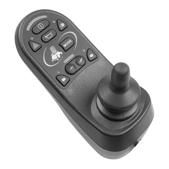
The control panel consists of a joystick and function buttons. At the front of the panel is the charger socket. Your wheelchair may also be equipped with an extra seat control panel in addition to the control panel. 6 - Joystick panel, R-net LED control panel... -
Page 7: Charger Socket
The control panel has a total of 9 function buttons and a joystick. 2.3.1 On/off button The on/off button turns on or off the wheelchair. 2.3.2 Horn button The horn will sound while this button is pressed. Joystick panel, R-net LED control panel - 7... -
Page 8: Button And Led For Maximum Speed Or Driving Profile
Alternatively, the button can be used to set the driving profile. 2.3.4 Mode button The mode button allows the user to navigate through the available operating modes for the control system. The number of modes available varies. 8 - Joystick panel, R-net LED control panel... -
Page 9: Hazard Warning Button And Led
This button turns on or off the wheelchair lights. Push the button to turn on the lights and push it again to turn them off. When activated, the LED indicator will illuminate. Joystick panel, R-net LED control panel - 9... -
Page 10: Left Turn Signal Button And Led
This button turn on or off the wheelchair’s right turn signal. Push the button to turn on the turn signal and push it again to turn it off. When activated, the LED indicator will flash in sync with the wheelchair’s turn signal. 10 - Joystick panel, R-net LED control panel... -
Page 11: Battery Voltage Indicator
The indicator shows a more precise value about one minute after you stop driving and are no longer using any power functions. The battery voltage indicator also functions as a fault indicator for the wheelchair’s electronics. Joystick panel, R-net LED control panel - 11... -
Page 12: Maximum Speed Indicator
In this case, the indicator LEDs will instead display the selected driving profile. There can be up to 5 driving profiles. The maximum speed or driving profile indicator also functions as a fault indicator for the wheelchair’s electronics. 12 - Joystick panel, R-net LED control panel... -
Page 13: Seat Indicator
On certain seats, the power seat lift, seat angle, backrest angle and leg rest angle functions are controlled by the control panel joystick. In this case, the active seat function is shown on the control panel seat indicator. Joystick panel, R-net LED control panel - 13... -
Page 14: Connectme
3 ConnectMe Important information IMPORTANT! Systems data can be transmitted WARNING! Activate flight mode where radio transmission is not allowed Flight mode ConnectMe contains a radio transmitter. In certain areas, radio transmission is not allowed and ConnectMe must be set to flight mode. 3.2.1 Activating flight mode Turn on the power wheelchair. - Page 15 2. Go into seat mode by using the mode button on the joystick or OMNI display. If the control panel does not have a mode button use the left paddle switch for mode selection. A switch plugged into the 1/8” monojack port of the joystick or OMNI display can also be used for mode selection.
- Page 16 5. The message Airplane Mode ON is shown on the display and the ConnectMe’s transmitting modem is off. The message will continue to show on the display as long as the flight mode is active. However, the wheelchair will work as normal. 6.
- Page 17 7. Push and hold the input device forward, or give and hold an equivalent command, for 5 seconds. 8. The yellow arrows will disappear and the message Airplane Mode ON is shown on the display and the ConnectMe’s transmitting modem is off. The message will continue to show on the display as long as the flight mode is active.
-
Page 18: Deactivating Flight Mode
3.2.2 Deactivating flight mode Turn on the power wheelchair. 2. Go into seat mode by using the mode button on the joystick or OMNI display. If the control panel does not have a mode button use the left paddle switch for mode selection. A switch plugged into the 1/8” monojack port of the joystick or OMNI display can also be used for mode selection. - Page 19 4. Push and hold the input device left for 15 seconds. A beep will sound. 5. The message Airplane Mode ON will disappear indicating that the flight mode is off. ConnectMe is now fully operational again. ConnectMe - 19...
-
Page 20: Turning Off Connectme Completely
6. Continue from here for an OMNI programmed for switched driver controls. Scroll through seat menus until M6 appears. 7. Push and hold the input device forward, or give and hold an equivalent command, for 5 seconds. Yellow arrows will appear, indicating that the ConnectMe’s transmitting modem is back on and that the flight mode is off. -
Page 21: Federal Communications Commission (Fcc)
Federal Communications Commission (FCC) statement This equipment has been tested and found to comply with the limits for a Class B digital device, pursuant to part 15 of the FCC rules. These limits are designed to provide reasonable protection against harmful interference in a residential installation. -
Page 22: Radiation Exposure Statement
3.4.1 Radiation Exposure statement This equipment complies with FCC radiation exposure limits set forth for an uncontrolled environment. End users must follow the specific operating instructions for satisfying RF exposure compliance. To maintain compliance with FCC RF exposure compliance requirements, please follow operation instruction as documented in this guide. - Page 23 Product approval ConnectMe fulfills the requirements of the following standards: EN 14971 EN 303 413 EN 60601-1 + A1 EN 50665 EN 300 328 EN 62311 EN 301 489-1 ISO 7176-9 EN 301 489-17 ISO 7176-14 EN 301 489-52 ISO 7176-21 EN 301 511 TS 134 124 EN 301 908-1...
- Page 26 336768 eng-CAN www.permobil.com...
Need help?
Do you have a question about the R-net LED and is the answer not in the manual?
Questions and answers