Table of Contents
Advertisement
Quick Links
Advertisement
Table of Contents

Subscribe to Our Youtube Channel
Related Manuals for Permobil R-net LCD colour


Summary of Contents for Permobil R-net LCD colour
- Page 1 R-net LCD colour User manual British English...
- Page 2 How to contact Permobil Introduction This user manual covers the functions of your R-net LCD colour Permobil Ltd. control panel and is intended as an extension to your power Unit 7, Polaris Centre, 41 Brownfields wheelchair’s user manual. Welwyn Garden City, Herts, AL7 1AN...
-
Page 3: Table Of Contents
Safety 2.7.8 Control system temperature 2.7.9 Motor temperature Types of warning signs 2.7.10 Hourglass Warning signs 2.7.11 Emergency stop Settings menu R-net control panel with LCD colour 2.8.1 Time display 2.8.2 Distance 2.8.3 Backlight General Charging socket Jack sockets Function buttons 2.4.1 On/Off button 2.4.2... -
Page 4: Safety
Safety Warning signs Types of warning signs WARNING! Always replace damaged The following types of warning signs are used in this manual: joystick covers Protect the wheelchair from exposure to any type of moisture, WARNING! including rain, snow, mud or spray. Indicates a hazardous situation which, if not avoided, could If any of the covers or the joystick boot has cracks or tears, it result in serious injury or death as well as damage to the... -
Page 5: Net Control Panel With Lcd Colour Display
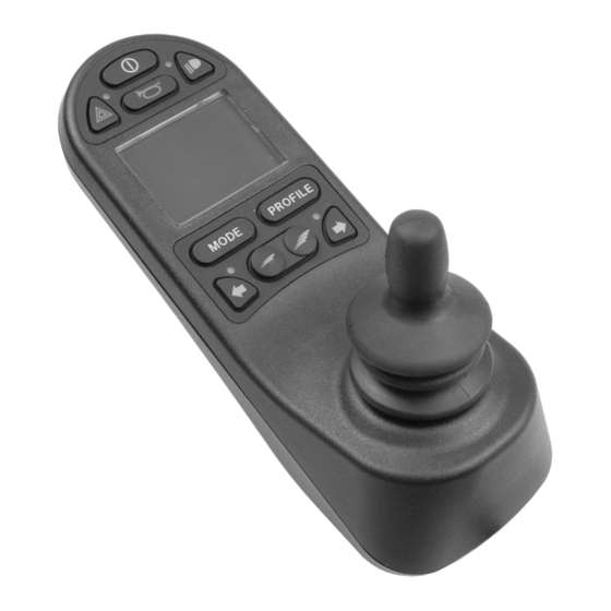
R-net control panel with LCD colour display General The control panel consists of a joystick, function buttons and a display. The charger socket is located at the front of the panel. Two jack sockets are located on the bottom of the panel. The control panel may have toggle switches at the bottom of the panel and/or a heavy-duty joystick that is larger than shown in the figure. -
Page 6: Charging Socket
Charging socket This socket should only be used for charging or locking the wheelchair. Do not connect any type of programming cable into this socket. This socket should not be used as a power supply for any other electrical device. Connecting other electrical devices may damage the control system or affect the wheelchair’s EMC (electromagnetic compatibility) performance. -
Page 7: Function Buttons
Function buttons 2.4.1 On/Off button The on/off button turns the wheelchair on or off. 2.4.2 Horn button The horn will sound while this button is pressed. 2.4.3 Maximum speed buttons These buttons decrease/increase the maximum speed of the wheelchair. Depending on the way the control system has been programmed, a screen can be displayed briefly when these buttons are pressed. -
Page 8: Hazard Warning Button And Led
2.4.6 Hazard warning button and LED Available if the wheelchair is provided with lights. This button turns the wheelchair hazard lights on or off. The hazard lights are used when the wheelchair is positioned such that it constitutes an obstruction for others. Push the button to turn on the hazard lights and push it again to turn them off. -
Page 9: Left Indicator Button And Led
2.4.8 Left indicator button and LED. Available if the wheelchair is provided with lights. This button turns the wheelchair’s left indicator on or off. Push the button to turn on the indicator and push it again to turn it off. When activated, the LED indicator will flash in sync with the wheelchair’s indicator. -
Page 10: Locking And Unlocking The Control System
Locking and unlocking the control system The control system can be locked in one of two ways, Either using a button sequence on the keypad or with a physical key. How the control system is locked depends on how your system is programmed. 2.5.1 Key locking To lock the wheelchair with a key lock:... -
Page 11: Keypad Locking
2.5.2 Keypad locking To lock the wheelchair using the keypad: • While the control system is turned on, press and hold the on/off button. • After 1 second, the control system will beep. Now release the On/Off button. • Deflect the joystick forwards until the control system beeps. •... -
Page 12: Seat Functions
Seat functions Not all seat functions are available on all seat models. On some seats, the seat functions can be controlled using the control panel joystick. Some models can memorise three seat positions. The seat adjustment mechanism stores each memorised seat position. This makes it easy to retrieve a seat position saved earlier. -
Page 13: Manoeuvring The Seat
2.6.2 Manoeuvring the seat Press the Mode button once or more times until a seat function icon appears in the control panel display. 2. Move the joystick to the left or right to select a seat function. The icon for the seat function selected appears in the display. -
Page 14: Memory
2.6.3 Memory 2.6.3.1 Saving a seat position to memory Some seat control systems can memorise three seat positions. The seat adjustment mechanism stores each memorised seat position. This makes it easy to retrieve a seat position saved earlier. This is how you save a seat position to memory: Adjust the seat function to the preferred position. - Page 15 2.6.3.2 Retrieving a seat position from the memory This is how you retrieve a seat position from memory: Press the Mode button once or more times until a seat function icon appears in the control panel display. 2. Move the joystick to the left or right to select a memorised position (M1, M2 or M3).
-
Page 16: Display
Display The status of the control system is shown on the display. The control system is on when the display is backlit. 2.7.1 Screen symbols The R-Net drive screen has common components that always appear, and components that only appear under certain conditions. Below is a view of a typical drive screen in profile 1. -
Page 17: Maximum Speed Indicator
2.7.3 Maximum speed indicator This displays the current maximum speed setting. The maximum speed setting is adjusted using the speed buttons. 2.7.4 Current profile The profile number describes which profile the control system is currently operating in. The profile text is the name or description of the profile the control system is currently operating in. -
Page 18: Control System Temperature
When the system is reset, the symbol disappears. When this symbol appears, drive slowly or stop the wheelchair. Permobil recommends that you drive slowly for a short period after the symbol has disappeared to prevent unnecessary strain on the wheelchair. -
Page 19: Settings Menu
Settings menu The settings menu permits the user to change, for example, the clock, display brightness, and background colour. Press and hold both speed buttons simultaneously to open the settings menu. Move the joystick to scroll through the menu. A right joystick deflection will enter a submenu with the related function options. -
Page 20: Distance
2.8.2 Distance The following section describes submenus related to distance. Total Distance this value is stored in the power module. It is related to the total distance driven during the time that the current power module has been installed in the chassis. -
Page 21: Backlight
2.8.3 Backlight The following section describes submenus related to the backlight. Backlight this sets the backlight on the screen. It can be set between 0% and 100%. Background sets the colour of the screen background. Blue is the standard, but in very bright sunlight the white background will make the display more visible. - Page 24 338962 eng-UK www.permobil.com...
Need help?
Do you have a question about the R-net LCD colour and is the answer not in the manual?
Questions and answers