Table of Contents
Advertisement
Quick Links
Advertisement
Table of Contents

Related Manuals for Memmert UF750DW


Summary of Contents for Memmert UF750DW
- Page 1 Operating manual UF750DW Universal oven dishwasher UF750DW www.memmert.com...
-
Page 2: Table Of Contents
Table of Contents Table of Contents 1. About this Manual 2. Safety 2.1 Terms and Symbols Used ............................2.1.1 Terms Used..............................2.1.2 Symbols Used .............................. 2.2 Product Safety and Dangers............................2.3 Requirements to be met by Operating Personnel......................2.4 Responsibility of the Owner ............................2.5 Product Use ................................ - Page 3 Table of Contents 4.6.4 Adjusting the Doors............................21 5. Putting into Operation 5.1 Putting into Operation for the First Time........................22 5.2 Connecting the Unit to the Power Supply ........................22 5.3 Switching on Unit ..............................23 6. Operation and Control 6.1 Operating Personnel..............................
- Page 4 Table of Contents 8.3.6 Shelf Type (Grid or metal plate)........................44 8.3.7 Balance ............................... 44 8.3.8 Remote Control ............................44 8.3.9 Gateway............................... 45 8.4 Date and Time................................45 8.5 Calibrate.................................. 46 8.5.1 Temperature Calibration ..........................46 8.6 Programme................................48 8.7 Acoustic Signals ..............................49 8.8 Log..................................
-
Page 5: About This Manual
Purpose and target audience This manual describes the design, function, transport, operation and maintenance of the product series Universal ovens UF750DW. It is intended for use by trained personnel employed by the owner who are tasked with operating and/or maintaining the unit. - Page 6 E-mail: sales@memmert.com www.memmert.com International After Sales Memmert GmbH + Co. KG Willi-Memmert-Straße 90-96 | D-91186 Büchenbach | Germany Tel. +49 9171 9792 911 E-mail: service@memmert.com www.memmert.com If you have any queries, please always quote the product number on the nameplate.
-
Page 7: Safety
Safety Safety Terms and Symbols Used In this manual and on the unit itself, certain recurring terms and symbols are used to warn you of hazards or give you information that is important in order to prevent injury or damage. To avoid accidents and damage, observe and follow these instructions. These terms and symbols are explained below. -
Page 8: Product Safety And Dangers
Safety Product Safety and Dangers The units described in this manual are technically sophisticated, manufactured using high- quality materials and subject to many hours of testing in the factory. They reflect the state of the art and comply with recognised technical safety regulations. However, there are still risks involved, even when the units are used as intended. -
Page 9: Requirements To Be Met By Operating Personnel
Safety WARNING Hot surfaces Depending on the operating situation, the unit and the load may be hot. Contact with hot surfaces may have serious health consequences due to burns! – Allow the unit to cool down. – Wear heat-resistant protective gloves when carrying out work. –... -
Page 10: Changes And Alterations
Safety Changes and Alterations Unauthorised changes or alterations must not be made to the appliance. Parts that are not approved by the manufacturer must not be mounted or built in. Unauthorised changes or alterations result in the CE declaration of conformity losing its validity, and the appliance must no longer be operated. -
Page 11: Construction And Description
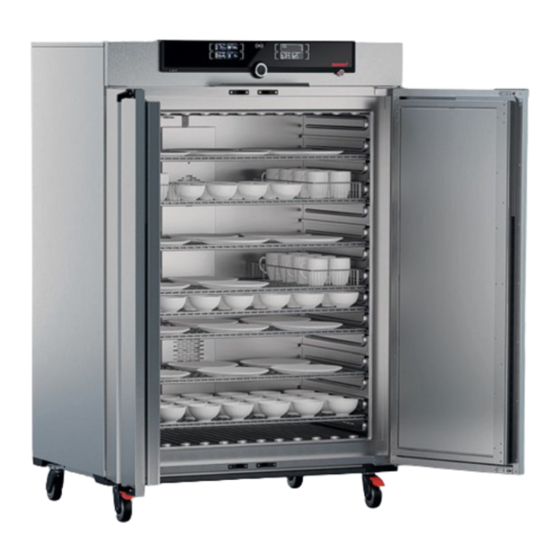
Construction and Description Construction and Description Design 1 ControlCOCKPIT mit kapazitiven 2 Hauptschalter Funktionstasten 3 Innenraumausstattung „Dishwasher“ 4 Rollen mit Feststellbremse 5 Typenschild 6 Türgriff 7 Drehknopf mit Bestätigungstaste 8 USB-Schnittstelle Description of Function Appliances of the xN type series feature natural ventilation (convection). For the xF type series, air is circulated by a fan mounted on the back panel of the chamber ③. -
Page 12: Materials
5 Fresh air Materials For the outer housing, MEMMERT processes stainless steel (Mat. No. 1.4016 – ASTM 430) for the chamber, stainless steel (Mat. No. 1.4301 – ASTM 304) is used, which stands out through its high stability, optimal hygienic properties and corrosion-resistance to many (but not all) chemical compounds (caution must be exercised with chlorine compounds, for example). -
Page 13: Connections And Interfaces
Construction and Description Connections and Interfaces 3.5.1 Electrical Connection This unit is designed for operation on an electrical power system with a maximum system impedance Z at the point of transfer (service line) of 0.292 Ohm. The operator must ensure that the unit is only operated on an electrical power system that meets these requirements. -
Page 14: Nameplate
Construction and Description Nameplate 1 Typbezeichnung 2 Betriebsspannung 3 Angewandte Norm 4 Schutzart 5 CE-Konformität 6 Herstelleranschrift 7 Entsorgungshinweis 8 Temperaturbereich 9 Anschluss- / Leistungswerte 10 Gerätenummer Technical Data Appliance size Stainless steel interior Volume Width 1,040 Height 1,200 Depth Max. -
Page 15: Applied Directives And Standards
We confirm that we always draw the attention of our suppliers to the legal restrictions on materials in accordance with our Company Standard for Material Compliance of Memmert GmbH + Co KG to ensure they take the original publications by the legislative authority into consideration at all times. -
Page 16: Ambient Conditions
3.8.2.1 REACH information of Memmert GmbH + Co. KG acc. to Regulation (EG) No. 1907/2006, Art. 33 Based on current knowledge, we confirm that products or sub-products containing substances of very high concern (SVHC in the specified components) in the Candidate List with concentrations higher than 0.1 mass % are installed in the appliances we supply:... - Page 17 Construction and Description Optional accessories Ethernet to USB converter. Makes it possible to connect the Ethernet port of the appliance ■ to the USB port of a computer/laptop. D57558 02/2024...
-
Page 18: Delivery, Transport And Setting Up
Delivery, Transport and Setting Up Delivery, Transport and Setting Up Safety CAUTION Lifting the appliance incorrectly The appliance is heavy. The appliance is heavy, so you could injure yourself if you try to lift it on your own. – Make sure that a sufficient number of people are on hand to lift and carry the appliance. -
Page 19: Unpacking
– Always attach the appliance to a wall with the anti-tilt bracket. – In case there is not enough space to fasten the appliance to a wall, do not put the appliance into operation and do not open the door. – Contact Memmert service. 4.6.1 Preconditions ü... -
Page 20: Installation Options
Delivery, Transport and Setting Up ü For appliances with castors or for appliances standing on sub frames with castors, always position the castors in a forward direction and lock the castor brakes to ensure that the appliances remain securely in place. See also 2 Technical Data [} 14] 2 Nameplate [} 14]... -
Page 21: Anti-Tilt Bracket
First, adjust the setting at the top of the door and, if this is not sufficient, adjust the bottom. A service video which explains how to adjust the door is available: www.memmert.com/de/downloads/media/service-videos/ 1. Open the door. 2. Loosen the screws. -
Page 22: Putting Into Operation
Putting into Operation Putting into Operation Putting into Operation for the First Time WARNING Condensation in the electrical components may cause short circuits. Due to temperature fluctuations during transport, condensation may form inside the unit. – After transporting or storing the unit in humid conditions, remove it from its packaging and allow it to acclimatise for at least 24 hours in normal ambient conditions. -
Page 23: Switching On Unit
Putting into Operation Switching on Unit 1. Switch on the appliance by pressing the main switch on the front of the appliance. ð The starting process is shown by three animated white dots (see }7.1 Warning Message of the Monitoring Function). After the first start-up, the appliance display is set to English by default. -
Page 24: Operation And Control
Operation and Control Operation and Control Operating Personnel The appliance may only be operated by persons who are of legal age and have been instructed accordingly. Personnel who are to be trained, instructed or who are undergoing general training may only work with the appliance under constant supervision of an experienced person. -
Page 25: Loading The Appliance
Operation and Control 2. To close the door, push the door closed and push the door handle to the side. Loading the Appliance WARNING Poisonous or explosive vapours and gases When loading the unit with an unsuitable load, poisonous or explosive vapours or gases may be produced. -
Page 26: Operating The Appliance
Operation and Control See also 2 Materials [} 12] Operating the Appliance 6.4.1 ControlCOCKPIT In manual operation, the desired parameters are entered at the ControlCOCKPIT on the front of the appliance. You can also make basic settings here (menu mode). Warning messages are also displayed, e.g. -
Page 27: Basic Operation
Operation and Control 13 Activation key for adjustment of interior lighting 14 Interior lighting display (additional option) (additional option) 15 Appliance state and programme display 16 Activation key for the appliance state 17 Activation key for adjustment of temperature 18 Temperature monitoring display monitoring 19 Graphic representation 20 Activation key for graphic representation... -
Page 28: Manual Mode
Operation and Control }6.5.2 Digital Backwards Counter ■ Programme Mode The appliance automatically runs programme sequences which have been defined using AtmoCONTROL software at a computer / laptop and then transferred to the appliance from a USB stick or via Ethernet. }6.5.3 Programme Mode ■... -
Page 29: Digital Backwards Counter
Operation and Control Air flap position Setting range: 0% (closed, recirculating operation) up to 100% (fully open, fresh air operation) in 10% increments. Fan speed Adjustment options: 0 to 100% in 10% increments Interior lighting (additional option) Adjustment options: on (100%) or off (0%) See also 2 Basic Operation [} 27] 2 Nameplate [} 14]... -
Page 30: Programme Mode
Operation and Control 4. Now, as described in }6.4.2 Basic Operation, set the individual reference values to be used by the appliance during operation. ð The change takes effect immediately. The set values can be changed at any time while the timer runs down. In Setup, you can choose if the timer should run setpoint-dependent or not, in other words, whether the timer should not start until a tolerance band around the setpoint temperature is reached or if it should start right after activation. - Page 31 Operation and Control Starting a programme 1. Press the activation key to the right of the status display. ð The current operating state is highlighted automatically, in this example manual mode ( ). 2. Turn the turn control until the start symbol is highlighted.
-
Page 32: Monitoring Function
Operation and Control End of programme The End display appears once the programme has finished normally. You can now restart the programme as described, ■ select another programme to run in menu mode (see }8.6 Programme) and run it as ■ described, return to manual mode. -
Page 33: Electronic Temperature Monitoring (Tww)
Operation and Control The acoustic alarm can be temporarily switched off by pressing the confirmation key until the next alarm event occurs. See also 2 Malfunctions, Warning and Error Messages [} 37] 2 Acoustic Signals [} 49] 6.6.2 Electronic Temperature Monitoring (TWW) The manually set min and max monitoring temperature of the electronic overtemperature protection is monitored by an temperature selector switch (TWW) protection class 3.1 acc. -
Page 34: Mechanical Temperature Monitoring: Temperature Limiter (Tb)
Operation and Control When the temperature leaves the set tolerance band around the setpoint – e.g. if the door is opened during operation (section B) – the alarm is triggered. The ASF alarm is automatically deactivated as soon as 50% of the set tolerance band of the setpoint has been reached again (section C). -
Page 35: Graph
Operation and Control The monitoring temperature must be set sufficiently high above the maximum setpoint temperature. We recommend 5 to 10 K. 5. Press the confirmation key to apply the setting for the upper alarm limit. ð The setting of the automatic temperature monitor (ASF) is automatically activated (auto). -
Page 36: Temperature Curve
Operation and Control 6.7.1 Temperature Curve 1. Press the activation key to the right of the GRAPH display. ð The display is enlarged and the temperature curve is displayed. 2. To change the time range to display press the activation key next to the arrow symbols. -
Page 37: Malfunctions, Warning And Error Messages
– Follow the measures listed in the event of a malfunction. – Contact Memmert International After Sales. Do not try to rectify appliance errors yourself; instead you should contact Memmert International After Sales or an authorised customer service point. In case of enquiries, please always state the model and appliance number on the nameplate (see }3.6 Nameplate). -
Page 38: Malfunctions, Operating Problems And Unit Errors
Malfunctions, Warning and Error Messages Description Cause Action Temperature alarm and TWB is displayed Temperature selector limiter (TWB) has Switch off the alarm by pressing the ■ switched off the heating permanently. confirmation button ■ Increase the difference between the monitoring temperature and the set point temperature –... -
Page 39: Power Failure
Malfunctions, Warning and Error Messages Error description Cause of errors Rectifying errors Start animation after switching on appears Cyan Notify customer service ■ in a colour other than not enough storage space on the SD card. white System files could not be loaded. Orange The fonts and images could not be loaded. -
Page 40: Menu Mode
Menu Mode Menu Mode In menu mode, you can make basic settings, load programmes and export protocols, as well as adjust the appliance. Before changing the menu settings, read the description of the respective functions on the following pages to avoid possible damage to the appliance and/or chamber load. ▶... -
Page 41: Setup
Menu Mode If no new values are entered or confirmed for approx. 30 seconds, the appliance automatically restores the former values. Activate the desired setting (in this example the language): 1. To do so, press the activation key to the left or right of the respective display. ð... -
Page 42: Ip Address And Subnet Mask
Menu Mode The heat output distribution (see }8.3.7 Balance) ■ ■ Remote control (see }8.3.8 Remote Control) Gateway (see }8.3.9 Gateway) ■ If the Setup menu contains more entries than can be displayed, this is indicated by the display “1/2”. This means that there is a second “page” of entries. To display the hidden entries, use the turn control to scroll beyond the lowest entry. -
Page 43: Unit
Menu Mode 3. With the turn control, set the new number, e.g. 255. 4. Confirm the selection by pressing the confirmation key. ð The next three digits of the IP address are automatically marked. ð They can now also be set according to the description above. 5. -
Page 44: Shelf Type (Grid Or Metal Plate)
Menu Mode 2 Digital Backwards Counter [} 29] 8.3.6 Shelf Type (Grid or metal plate) Here, you have to set the type of shelf (grid or metal panel) used. The selection Metal panel enables you to adjust the closed-loop control function to the different air flow characteristics in the chamber when using optional shelves instead of the grids provided as standard. -
Page 45: Gateway
Menu Mode When the appliance is in remote control mode, the symbol appears in the temperature display. In the settings Write + Read and Write + Alarm, the appliance cannot be controlled at the ControlCOCKPIT until the remote control has been switched off (Off setting) or set to Read Only. -
Page 46: Calibrate
Menu Mode 7. Confirm the selection by pressing the confirmation key. ð The adjustment options are highlighted. 8. Set summertime to off (✕) or on (✓) with the turn control – in this case on (✓). 9. Save the setting by pressing the confirmation key. The changeover between summer and winter time does not take place automatically. - Page 47 Menu Mode Example: Temperature deviation should be corrected 1. Press the activation key to the right of the CALIB display. ð The display is enlarged and the temperature adjustment option is automatically highlighted. 2. Press the confirmation key repeatedly, until the calibration temperature Cal2 is highlighted.
-
Page 48: Programme
Menu Mode 10. Wait until the appliance reaches and displays the setpoint temperature. ■ The reference instrument will display the corresponding deviation. 11. In the SETUP, adjust the calibration correction value Cal2 to the deviation temperature (actual value measured minus setpoint value). 12. -
Page 49: Acoustic Signals
Menu Mode As soon as the programme is ready, Select is highlighted once again. To start the programme: 6. Return to the operating mode by pressing the MENU key again. 7. Start the programme as described in }6.5.3 Programme Mode. You can now remove the USB storage medium. To delete a programme: 8. -
Page 50: Log
Menu Mode 4. Save the setting by pressing the confirmation key. If an acoustic signal sounds, it can be turned off by pressing the confirmation key. NOTICE The supplied manual for AtmoCONTROL describes how – to import exported log data into AtmoCONTROL, –... -
Page 51: User Id
Menu Mode USER ID 8.9.1 Description With the USER ID function, you can lock the settings of individual (e.g. temperature) or all parameters, so that they cannot be changed at the appliance by accident or by unauthorised persons. You can also lock adjustment options in Menu mode (e.g. adjustment of date and time settings). -
Page 52: Maintenance And Servicing
Maintenance and Servicing Maintenance and Servicing DANGER Danger of suffocation inside the appliance If the appliances is a certain size, you can get accidentally locked in, which is potentially life-threatening. – Do not climb into the appliance. – Do not carry out cleaning work in the chamber alone. DANGER Live parts When covers are removed, live parts are exposed and contact with these parts may result... -
Page 53: Repairs And Service
Maintenance and Servicing Repairs and Service Repairs and service work may only be carried out by specialist Memmert personnel and qualified service providers. NOTICE Repairs and service work are described in a separate service manual. D57558 02/2024... -
Page 54: Storage, Transport And Disposal
Storage, Transport and Disposal Storage, Transport and Disposal 10.1 Storage and Transport The appliance may only be stored and transported under the following conditions: ■ in a dry enclosed, dust-free room ■ disconnected from the power supply 10.2 Disposal This product is subject to Directive 2012/19/EC on Waste Electrical and Electronic Equipment (WEEE) of the European Parliament and EU Council of Ministers. - Page 55 Notes D57558 02/2024...
- Page 56 Operating manual Universal oven dishwasher UF750DW D57558 Effective 02/2024 English...
Need help?
Do you have a question about the UF750DW and is the answer not in the manual?
Questions and answers