Advertisement

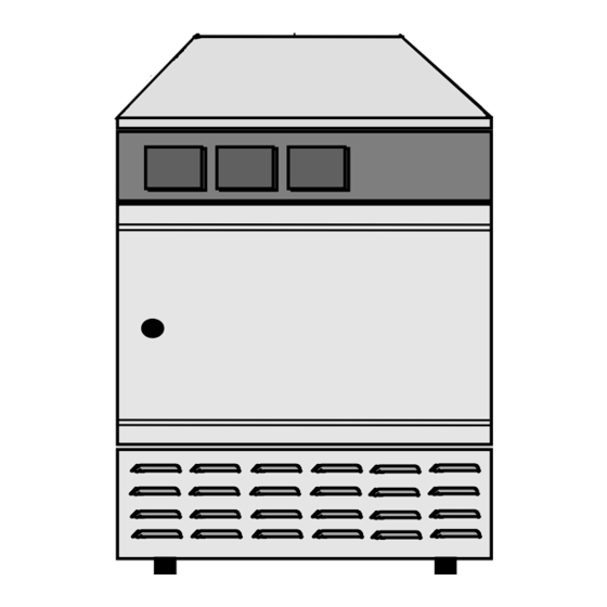
SERVICEMANUAL
UE/BE 200 - 800
SE 200 - 400
ULE/SLE 400 - 800
UP/BP/ULP/SLP 400 - 800
08 / 98

Advertisement

Table of Contents
loading
Need help?

Need help?

Do you have a question about the UE 200 and is the answer not in the manual?

Questions and answers

Summary of Contents for Memmert UE 200

  • Page 1 SERVICEMANUAL UE/BE 200 - 800 SE 200 - 400 ULE/SLE 400 - 800 UP/BP/ULP/SLP 400 - 800 08 / 98...
  • Page 2: Table Of Contents

    Table of contents Removing the top cover....................2 Changing of “Main switch” module (see chap. 4) ..........2 Changing of control panel ..................3 Front panel "Main switch" E - class.................4 Changing the safety device module TWW / TWB (only E-class) ......4 Changing the temperature sensor PT100 for electronic controller ......5 Changing the controller module ................6 7.1 Removing the working controller module / Class E..........6 7.2 Removing the working controller module Class P..........7...
  • Page 3: Removing The Top Cover

    Instructions for repair This Service manual contains instructions for the repair of MEMMERT ovens. For maintenance work please see the Operation Instructions added to each unit. We point out that tasks which require disassembly (even in part) of the unit have to be carried out by experts only.
  • Page 4: Changing Of Control Panel

    Changing of control panel Remove top cover (see chap. 1) Disconnect all cables from main switch, temperature controller and safety device unit. Open the door. On the right upper door hinge unscrew the left one of the two screws (1) approx. 5 mm. Slide the control panel to the left and remove it forwards with all control modules (main switch, temperature controller and safety device).
  • Page 5: Front Panel "Main Switch" E - Class

    Front panel "Main switch" E - class Front panel Switch Adjusting shaft for ventilation flap Cable connectors switch Pilot lamps Flat spring Cable connectors pilot lamps Bearing bracket Adjusting spindle Mounting blocks Slider Switch knob Lock washer for bearing bracket Instead of marked parts P-units contain a card reader for MEMory...
  • Page 6: Changing The Temperature Sensor Pt100 For Electronic Controller

    Safety device Cable connectors safety device Temperature sensor Changing the temperature sensor PT100 for electronic controller Remove top cover (see chap. 1) The temperature sensor can carefully be moved backwards out of the clamp with a tool and can be taken out through the ceiling and/or the back panel of the working chamber.
  • Page 7: Changing The Controller Module

    Changing the controller module Unlock the electronic controller modules by pressing the two locking latches together. Tilt controller forward and lift it slightly. Pull out complete controller frame to the front. 7.1 Removing the working controller module / Class E Working controller Safety device Additional power board...
  • Page 8: Removing The Working Controller Module Class P

    7.2 Removing the working controller module Class P Working controller Cable connectors working controller Safety device Fixing screws additional power board Additional power board Temperature sensors working controller and safety device Ribbon cable safety device ↔ additional power board Ribbon cable to serial interface and MEMory reader Ribbon cable to parallel printer interface Ribbon cable working controller ↔...
  • Page 9: Removing The Temperature Limiter/ Class P

    Removing the temperature limiter / Class P Remove top cover (see chap. 1). Remove rear wall (chap. 15). Push temperature sensor (2) carefully out of the clip with a tool and pull it up through the intermediate plate. Disconnect all cable connectors (3) at the temperature limiter (1).
  • Page 10: Changing The Fan Motor

    10 Changing the motor fan To change the circulation fan, first remove the ventilating shaft cover (1) in the working chamber after releasing the two screws (2). The fan blade (3) can be pulled off after removing the cap nut (4) (Note! Left-hand thread).
  • Page 11: Changing The Door Lock, Door Knob And / Or Door Seal

    11 Changing the door lock, door knob and / or door seal 11.1 Changing the door lock, door knob and / or door seal on models 200 - 500 11.1.1 Door lock Unscrew the lock cover (10). Pull out the radiation shield (8) with door seal (7). The door lock can be dismantled in order of numbers 11 to 14 and 2 to 3 and assembled in reverse order.
  • Page 12: Changing The Door Lock, Door Knob And / Or Door Seal On Models 600 - 800

    11.2 Changing the door lock, door knob and / or door seal on models 600 - 800 11.2.1 Door lock Unscrew the screws (8) and (9). Pull out radiation shield (10) with door seal (7). The door lock can be dismantled in order of numbers 11 to 14 and 2 to 3 and assembled in reverse order.
  • Page 13: Dismantling The Door

    12 Dismantling the door Unscrew the screws (2). Pull out the door (1) horizontally in the direction of the arrow. When assembling the door please note: Lubricate the moving parts of the door hinges with thin silicone grease (see also chap. "Maintenance"...
  • Page 14: Changing The Seal Of The Working Chamber

    13 Changing the seal of the working chamber The seal of the working chamber can be pulled out after opening the door. The new one can be fitted in according to the illustration. The pre-cut seal should be inserted into the space without tension and then cut if required.
  • Page 15: Dismantling The Unit

    15 Dismantling the unit - page 16 Remove the door (see. chap. 12). Remove the inner door on incubators (see chap. 14). Remove the top cover (3) (see chap. 1). Disconnect the protective ground contacts from the side panels and the rear wall of the casing cover.
  • Page 16 The heating panels can then be removed in the order indicated by the numbers, and the heating can be replaced according to the heating diagram and inserted. Secure the new heating coil with aluminium adhesive tape (supplied with the heating elements).
  • Page 17 Cage Control panel Top cover Side panels Rear wall Intermediate plate Air inlet Air shaft Insulating mat top Insulating mats sides Insulating mat back Adjusting spindle for ventilation flap Heating Circulation fan (only UL ovens) Working chamber Air outlet Heating sheets UE/BE 200-800, SE 200-400, ULE/SLE 400-800 UP/BP/ULP/SLP 400-800...
  • Page 18: Dismantling The Working Chamber

    17 Dismantling the working chamber The so-called transit fitting must be removed only if the working chamber has to be dismantled from the housing cage. Pull out upwards both side panels (4). Unscrew screws (2). Remove the transit fitting (1). Release the tubing clips by pressing against the inner walls of the working chamber.
  • Page 19: Rectifying Faults In Electronic Working Controllers

    The following measures support debugging: Fault Procedure E-Class P-Class E - 0 Send controller back to Memmert for replacement E - 1 E R R - 1 Send controller back to Memmert for replacement E - 2 E R R - 2 Check the equipment fuses and if necessary replace them as described in Chap.
  • Page 20: Our Address

    Any warranty and claims for damage are excluded if these instructions are disregarded. We reserve the right to make changes in technical specifications. Dimensions subject to confirmation. 19 Our Address MEMMERT GmbH + Co.KG P.O.Box 17 20, 91107 Schwabach Federal Republic of Germany +49 9122/925-0 Fax +49 9122/14585 Internet: www.memmert.com...
  • Page 21: Spare Part List

    20 Spare part list inner glass door model 600 right B03447 Chap.4 mounting block E00242 left B03399 switch knob E03613 right B03449 switch B03254 left B03448 pilot lamp 115V 230V right B03451 E03608 E03567 left B03450 yellow E03610 E03569 inner door hinge topside B02902 green...
  • Page 22: Index

    21 Index additional power board......6, 7 lock cover ..........10 air inlet ..........14, 20 lock washers..........2 air outlet ............ 14 locking latches..........6 bearing bracket ........... 4 maintenance work ........2 MEMory Card ..........18 modules safety device......4, 7 cable connectors switch......4 modules working controller......6, 7 cardboard disc ..........
  • Page 23 UE/BE 200-800, SE 200-400, ULE/SLE 400-800 UP/BP/ULP/SLP 400-800...
  • Page 24 D 08364 UE/BE 200-800, SE 200-400, ULE/SLE 400-800 UP/BP/ULP/SLP 400-800...

Table of Contents