Rockwell Automation Allen-Bradley 2711T-B10I1N1 Quick Start Manual
Second-generation mobileview tethered operator terminal
Hide thumbs
Also See for Allen-Bradley 2711T-B10I1N1:
- User manual (104 pages) ,
- Quick start manual (48 pages)
Table of Contents
Advertisement
Quick Links
Quick Start
Original Instructions
Second-generation MobileView Tethered Operator Terminal
Catalog Numbers 2711T-B10I1N1, 2711T-T10I1N1-TC
Topic
The following publication provides a brief overview of how to install and operate the second-generation MobileView™
2711T terminal. For more detailed information on this terminal, refer to MobileView 2711T Tethered Operator Terminal
User Manual, publication 2711T-UM001, which is available online at https://rok.auto/literature.
This quick start publication must be kept throughout the entire service life of
the second-generation MobileView 2711T terminal.
Summary of Changes
This quick start publication contains new and updated information as indicated in the following table.
Topic
Page
2
2
3
6
11
29
40
41
43
44
45
46
47
Page
28
45
Advertisement
Chapters
Table of Contents

Related Manuals for Rockwell Automation Allen-Bradley 2711T-B10I1N1


Summary of Contents for Rockwell Automation Allen-Bradley 2711T-B10I1N1
-
Page 1: Table Of Contents
Quick Start Original Instructions Second-generation MobileView Tethered Operator Terminal Catalog Numbers 2711T-B10I1N1, 2711T-T10I1N1-TC Topic Page MobileView 2711T Terminal Dimensions and Weight MobileView 2711T Terminal Component Description Safety Precautions and Elements The Second-generation MobileView 2711T Terminal The MobileView IP65 Junction Box Initial Power-up of the Second-generation MobileView 2711T Terminal Shut Down the Second-generation MobileView 2711T Terminal MobileView Mounting Brackets... -
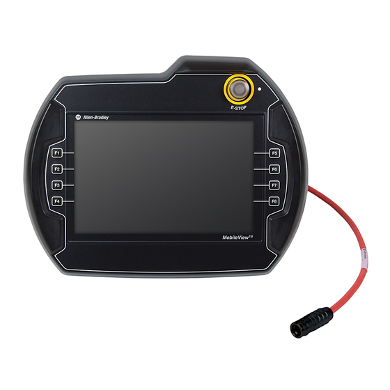
Page 2: Mobileview 2711T Terminal Dimensions And Weight
3-position, twin circuit, enabling switch for safety system interface • – Plug for alternate cable outlet not used (meets degree protection IP65) • – Back cover to access connection compartment • – The 2711T-T10I1N1-TC MobileView terminal does not have this feature. Rockwell Automation Publication 2711T-QS002F-EN-P - February 2024... -
Page 3: Safety Precautions And Elements
ATTENTION: Personnel responsible for the application of safety-related Programmable Electronic Systems (PES) shall be aware of the safety requirements in the application of the system and shall be trained in using the system. Rockwell Automation Publication 2711T-QS002F-EN-P - February 2024... - Page 4 (the enabling switch must not be in the enabling position). • The enabling switch must be released within a defined time period and pushed into the enabling position again, with the time length defined by the activity. Rockwell Automation Publication 2711T-QS002F-EN-P - February 2024...
- Page 5 For the risk assessment for the machinery, use the standards in ISO 12100, ‘Safety of machinery - General principles for design - Risk assessment and risk reduction.’ The control system must be designed for the safety level that results from the risk assessment of ISO 12100. Rockwell Automation Publication 2711T-QS002F-EN-P - February 2024...
-
Page 6: The Second-Generation Mobileview 2711T Terminal
Back Cover Carefully lift off the back cover and set it aside. Figure on page 7 shows the main circuit board of the second-generation MobileView 2711T terminal with the back cover removed. Rockwell Automation Publication 2711T-QS002F-EN-P - February 2024... - Page 7 • Torx T10 screwdriver • 8 mm hex key To install the cable, perform the following steps. Decide on which cable-connection port of the terminal to install the cable; see Figure on page Rockwell Automation Publication 2711T-QS002F-EN-P - February 2024...
- Page 8 Do not force the cable terminals through the channel. If you encounter resistance, slowly pull the cable towards you until it moves freely again. If necessary, slide the connector-cable assembly farther down the cable to assist cable feed through the channel. Rockwell Automation Publication 2711T-QS002F-EN-P - February 2024...
- Page 9 50 mm ±2 (2 in. ±0.08) 10 mm ±2 (0.4 in. ±0.08) S1 (cable connector) Connection Cable 18 19 40 mm ±3 5, 10, or 15 m (1.6 in. ±0.12) (16.4, 32.8, or 49.2 ft) Rockwell Automation Publication 2711T-QS002F-EN-P - February 2024...
- Page 10 RD+ (receive) n Interface RD- (receive) violet E-stop, illuminated (+) white-pink E-stop, illuminated (–) Illuminated white Semi-wireless jumper Push Button blue Semi-wireless jumper white-blue Box ID Bridge — Bridge — Not used Shielded. Rockwell Automation Publication 2711T-QS002F-EN-P - February 2024...
-
Page 11: The Mobileview Ip65 Junction Box
2711T-JBIP65DC1 junction box. The cover plate is fitted with a seal. To maintain a tight seal and the IP65 rating (when installed on an IP65-rated control cabinet), install the cover plate on an even surface. Rockwell Automation Publication 2711T-QS002F-EN-P - February 2024... - Page 12 Determine where to mount the junction box. Use the dimensions in Figure on page 13 to decide where to locate the junction box in a safe area that is easily accessible for a terminal operator. Rockwell Automation Publication 2711T-QS002F-EN-P - February 2024...
-
Page 13: Temporarily Mount The Ip65 Junction Box
2711T-JBIP65DM1, the IP65 junction box with M12 On-Machine connections You can slide the IP65 junction box onto the longer screw bosses of the mounted back plate; no screws are needed. Longer Screw Boss Rockwell Automation Publication 2711T-QS002F-EN-P - February 2024... -
Page 14: Wire The 2711T-Jbip65Dc1 Junction Box
Place the corresponding seal rings over each wire. Place the corresponding cable gland over each wire. Feed each wire through the corresponding cable outlet. page 15 for where to attach each wire to the appropriate terminal. Rockwell Automation Publication 2711T-QS002F-EN-P - February 2024... - Page 15 6-pin terminal for an application or control system where multiple IP65 junction boxes are used. This terminal helps identify which IP65 junction box has a second-generation MobileView terminal that is attached to it. For more details, S10 Terminal Pin Descriptions on page Rockwell Automation Publication 2711T-QS002F-EN-P - February 2024...
- Page 16 The two Ethernet connectors on the IP65 junction box provide connection to an Ethernet network. Each connector uses an 8-pin, RJ45 modular jack connector. Pinouts are as follows. Pin # Ethernet Signal Pin # Ethernet Signal Not used Not used Not used Not used Rockwell Automation Publication 2711T-QS002F-EN-P - February 2024...
- Page 17 MobileView terminal that is connected to it. KEY3 KEY2 Not used. KEY1 KEY0 IMPORTANT The DRY contact signal can be used in the control application and is only designed for purposes that are not safety related. Rockwell Automation Publication 2711T-QS002F-EN-P - February 2024...
-
Page 18: Configure The 2711T-Jbip65Dc1 Junction Box
MobileView terminals with gray push buttons, cat. nos. 2711T-F10G1N1 and 2711T-T10G1N1) Activate DIP switch 8 The MobileView terminal to be used has no Box ID functionality but has an illuminated E-stop button Rockwell Automation Publication 2711T-QS002F-EN-P - February 2024... - Page 19 With the two address switches, you can set Box IDs from 0 to 255 as hexadecimal values. To use Box ID functionality with FactoryTalk® View ME software, access the Rockwell Automation Knowledgebase link rok.auto/knowledgebase and search for AID 1043633.
-
Page 20: Configure The 2711T-Jbip65Dm1 Junction Box
IP65 rating, verify that the junction box is seated properly to the cover plate. Mount the junction box to its back plate with the six supplied screws. Torque the six screws to 0.85…1.15 N•m (7.5…10.2 lb•in). Rockwell Automation Publication 2711T-QS002F-EN-P - February 2024... -
Page 21: Connect M12 On-Machine Connectors To The 2711T-Jbip65Dm1 Junction Box
For the D-code M12 female network connectors, use polyamide small-body unshielded or zinc die-cast large-body shielded mating connectors. If you use shielded (STP) cable with metal housing, isolate the shield at the junction box end of the cable to minimize ground offsets. Rockwell Automation Publication 2711T-QS002F-EN-P - February 2024... -
Page 22: Connect Power To Ip65 Junction Boxes
Verify that the power status indicator on the front of the IP65 junction box is lit and green. Verify that the Ethernet status indicator on the front of the IP65 junction box is lit and green. Connect a second-generation MobileView terminal. Rockwell Automation Publication 2711T-QS002F-EN-P - February 2024... - Page 23 WARNING: An IP65 junction box does not protect against the restart of a system or machine. Separate protection must be provided on the system or machine, such as an Acknowledgment key. Rockwell Automation Publication 2711T-QS002F-EN-P - February 2024...
-
Page 24: Ip65 Junction Box Status Indicator Lights
A second-generation MobileView terminal without an illuminated E-stop button is connected No color to the junction box. Green The junction box is connected to an Ethernet network. Ethernet No color The junction box is not connected to an Ethernet network. Rockwell Automation Publication 2711T-QS002F-EN-P - February 2024... - Page 25 ATTENTION: Other colors signify when a second-generation MobileView terminal or IP65 junction box are in an error state. To identify these colors, see the Troubleshooting section in the MobileView Tethered Operator Terminal User Manual, publication 2711T-UM001. Rockwell Automation Publication 2711T-QS002F-EN-P - February 2024...
- Page 26 10 seconds You must first configure an IP65 junction box to recognize an illuminated E-stop push button on a second-generation MobileView terminal. For more information, see DIP Switch on page Rockwell Automation Publication 2711T-QS002F-EN-P - February 2024...
-
Page 27: Connect A Second-Generation Mobileview Terminal To An Ip65 Junction Box
MobileView terminals 2711T-F10G1N1 and 2711T-T10G1N1, and both IP65 junction boxes. You cannot use a silver 22-pin connection cable with first generation MobileView terminals 2711T-B10K1N1, 2711T-B10M1N1, and 2711T-T10R1N1, or an IP20 junction box. Rockwell Automation Publication 2711T-QS002F-EN-P - February 2024... -
Page 28: Updated Color Description For Cable Connector And Junction Box Connector
The Ethernet connector on IP65 junction boxes provides a connection to an Ethernet network. The connector uses an 8-pin, RJ45 modular jack connector. To connect to an Ethernet network, see Ethernet (ETH3, ETH2) Connections on page Rockwell Automation Publication 2711T-QS002F-EN-P - February 2024... -
Page 29: Initial Power-Up Of The Second-Generation Mobileview 2711T Terminal
IP65 junction box, a status indicator light on the terminal next to the E- stop is illuminated green. When a second-generation MobileView 2711T terminal is powered up, a dark screen is present for several seconds between the startup screen and the next available screen. Rockwell Automation Publication 2711T-QS002F-EN-P - February 2024... - Page 30 Do not disconnect power from the second-generation MobileView 2711T terminal until after the Windows End User Setup procedure is completed. If power is disconnected during this procedure, it can result in a corrupted system image. Rockwell Automation Publication 2711T-QS002F-EN-P - February 2024...
- Page 31 An account password is recommended but not mandatory; if you do not want one, press Next. After you add information, press Next. A license-terms dialog box appears. The license terms apply to Microsoft® Windows® Embedded Standard 7 operating system and all Allen-Bradley software content. Rockwell Automation Publication 2711T-QS002F-EN-P - February 2024...
- Page 32 Press to check the ‘I accept the licensed terms’ box, and press Next. Choose your appropriate date and time settings, and press Next. A popup dialog box appears, ‘Windows is finalizing your settings.’ When completed, the second-generation MobileView 2711T terminal desktop appears. Rockwell Automation Publication 2711T-QS002F-EN-P - February 2024...
- Page 33 Before you configure applications on the second-generation MobileView 2711T terminal, verify that EWF is disabled. On the terminal desktop taskbar, the EWF status icon is unlocked when EWF is disabled. Rockwell Automation Publication 2711T-QS002F-EN-P - February 2024...
- Page 34 By default, EWF is disabled. EWF must be disabled or any application changes are lost when the second-generation MobileView 2711T terminal is powered down. Rockwell Automation recommends that you enable EWF to preserve operating system and application integrity, especially for where the terminal is expected to be frequently connected and disconnected from junction boxes.
- Page 35 Connections to access the same screen. Touch and hold for about 3 seconds, and then release. A pull-down menu appears. Press Properties. On the Properties dialog box, press to select Internet Protocol Version 4 (TCP/IPv4). Press Properties. Rockwell Automation Publication 2711T-QS002F-EN-P - February 2024...
- Page 36 Enhanced Write Filter (EWF) on page To initially configure FactoryTalk View ME Station, perform the following steps. Create a runtime application file (MER) with FactoryTalk View Studio software. Within FactoryTalk View Studio software, launch the transfer utility. Rockwell Automation Publication 2711T-QS002F-EN-P - February 2024...
- Page 37 • Select your second-generation MobileView terminal as the destination terminal (C). • Click Download (D). See the graphic with step 6 page 38 to view the MER file location on the SD card. Rockwell Automation Publication 2711T-QS002F-EN-P - February 2024...
- Page 38 10. If desired, press Application Settings or F3 to configure FactoryTalk View ME Station application-specific settings (for example, device shortcuts or startup language). Press the second-generation MobileView terminal desktop to access EWF Manager and enable EWF; see page 33 for how to enable EWF. Rockwell Automation Publication 2711T-QS002F-EN-P - February 2024...
- Page 39 From the second-generation MobileView 2711T terminal desktop, press Touch Configuration. On the Touch tab of the Pen and Touch dialog box, press Press and hold. With Press and hold highlighted, press Settings. Clear the Enable press and hold for right-clicking checkbox. Rockwell Automation Publication 2711T-QS002F-EN-P - February 2024...
-
Page 40: Shut Down The Second-Generation Mobileview 2711T Terminal
If you disabled EWF to make application changes, then you must enable EWF again before you shut down the second-generation MobileView 2711T terminal. Review Enhanced Write Filter (EWF) on page 33 before you shut down the second-generation MobileView 2711T terminal. Rockwell Automation Publication 2711T-QS002F-EN-P - February 2024... -
Page 41: Mobileview Mounting Brackets
This bracket is when locked storage is preferred. Each mounting bracket ships with a cutout template for installation; 2711T-DS001 with the standard mounting bracket 2711T-DS003 for the VESA mounting bracket. Rockwell Automation Publication 2711T-QS002F-EN-P - February 2024... - Page 42 118 (4.6) 365 (14.4) 161 (6.3) 200 (7.9) 118 (4.6) 365 (14.4) 161 (6.3) 393 (15.5) 453 (17.8) 393 (15.5) 453 (17.8) Standard Mounting Bracket VESA Mounting Bracket (cat. no. 2711T-BRACKET) (cat. no. 2711T-VMBRACKET) Rockwell Automation Publication 2711T-QS002F-EN-P - February 2024...
-
Page 43: European Communities (Ec) Directive Compliance
Second-generation MobileView Tethered Operator Terminal Quick Start European Communities (EC) Directive Compliance Rockwell Automation hereby declares that second-generation MobileView 2711T terminals with E-stop functionality are in conformity with Directive 2006/42/EC as specified in the Declaration of Conformity available from rok.auto/certifications. -
Page 44: Second-Generation Mobileview Terminal Specifications
Supply voltage tolerance range 19.2…30V DC (EN 61131-2) Input current 500 mA at 24V DC Peak inrush current 5.6 A (max) 5000 (typical) Cycle duration Applies only to the connection cable connector and the junction box. Rockwell Automation Publication 2711T-QS002F-EN-P - February 2024... -
Page 45: Ip65 Junction Box Specifications
To adjust the display brightness and GPU energy setting, see the MobileView Tethered Operator Terminal User Manual, publication 2711T-UM001. If you need assistance setting CPU and GPU ratings, contact your local Rockwell Automation sales office or Allen-Bradley distributor. IP65 Junction Box Specifications General Cat. -
Page 46: Mobileview Accessories
VESA mounting bracket for stationary operation or locked storage of the terminal. 2711T-22JUMP A black, 22-pin bridge connector to bypass E-stop contactors in an IP65 MobileView junction box. For applications where the customer plans to move one MobileView terminal between many MobileView junction boxes. Rockwell Automation Publication 2711T-QS002F-EN-P - February 2024... -
Page 47: Additional Resources
Second-generation MobileView Tethered Operator Terminal Quick Start Additional Resources These documents contain more information about related products from Rockwell Automation. Resource Description MobileView Tethered Operator Terminal User Manual, Provides information to install, operate, and troubleshoot publication 2711T-UM001 MobileView 2711T terminals and junction boxes. - Page 48 At the end of life, this equipment should be collected separately from any unsorted municipal waste. Rockwell Automation maintains current product environmental compliance information on its website at rok.auto/pec. Your comments help us serve your documentation needs better. If you have any suggestions on how to improve our content, complete the form at rok.auto/docfeedback.
Need help?
Do you have a question about the Allen-Bradley 2711T-B10I1N1 and is the answer not in the manual?
Questions and answers