Table of Contents
Advertisement
Quick Links
Advertisement
Table of Contents

Subscribe to Our Youtube Channel
Related Manuals for Pfeiffer Vacuum HIPACE 10 NEO


Summary of Contents for Pfeiffer Vacuum HIPACE 10 NEO
- Page 1 OPERATING INSTRUCTIONS Translation of the Original HIPACE 10 NEO Turbopump...
-
Page 2: Changing Operating Fluid Reservoir On Bearing Side
Dear Customer, Thank you for choosing a Pfeiffer Vacuum product. Your new turbopump is designed to support you by its performance, its perfect operation and without interfering your individual application. The name Pfeiffer Vacuum stands for high-quality vacuum technology, a comprehensive and complete range of top-quality products and first-class service. -
Page 3: Table Of Contents
Connecting fore-vacuum side Connecting accessories Connecting the electrical supply 5.5.1 Ground the vacuum pump 5.5.2 Establishing electric connection Operation Commissioning Operating modes 6.2.1 Operation without operating unit 6.2.2 Operation via multi-function connection "X3" 6.2.3 Operation via Pfeiffer Vacuum control unit 3/54... - Page 4 Shutting down for longer periods Recommissioning Recycling and disposal General disposal information Dispose of turbopumps Malfunctions Service solutions by Pfeiffer Vacuum Spare parts, HiPace 10 Neo Accessories 13.1 Accessory information 13.2 Ordering accessories Technical data and dimensions 14.1 General 14.2 Technical data 14.3 Substances in contact with the media...
- Page 5 Troubleshooting turbopumps Tbl. 12: Available spare parts Tbl. 13: Accessories Tbl. 14: Conversion table: Pressure units Tbl. 15: Conversion table: Units for gas throughput Tbl. 16: HiPace 10 Neo Tbl. 17: Materials that make contact with the process media 5/54...
- Page 6 Removing operating fluid reservoir Fig. 13: Assembling operating fluid reservoir Fig. 14: Installing and removing the electronic drive unit TC 80 Fig. 15: Spare parts, HiPace 10 Neo Fig. 16: HiPace 10 Neo | TC 80 | DN 40 ISO-K 6/54...
-
Page 7: About This Manual
Keep the manual for future consultation. 1.1 Validity These operating instructions are a customer document of Pfeiffer Vacuum. The operating instructions describe the functions of the named product and provide the most important information for the safe use of the device. The description is written in accordance with the valid directives. The information in these operating instructions refers to the product's current development status. -
Page 8: Abbreviations
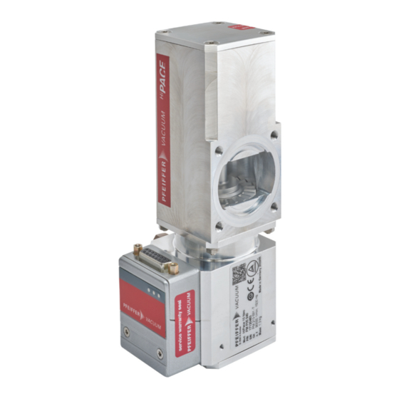
1 Warning sign "Risk of injury with high vacuum con- Information regarding ground connection nection open" 2 Warranty seal Rating plate 3 Banner with Pfeiffer Vacuum logo Operating instructions note 1.3.3 Abbreviations Abbreviation Meaning in this document Diameter value (in mm) -
Page 9: Instructions In The Text
About this manual Abbreviation Meaning in this document High vacuum flange, high vacuum side Flange: Connection in accordance with ISO 1609 and ISO 2861 Light emitting diode Functional earth [P:xxx] Electronic drive unit control parameters. Printed in bold as a three-digit number in square brackets. -
Page 10: Safety
Safety 2 Safety 2.1 General safety information The following 4 risk levels and 1 information level are taken into account in this document. DANGER Immediately pending danger Indicates an immediately pending danger that will result in death or serious injury if not observed. ►... - Page 11 Safety Risks during installation DANGER Danger to life from electric shock Power supply packs that are not specified or are not approved will lead to severe injury to death. ► Make sure that the power supply pack meets the requirements for double isolation between mains input voltage and output voltage, in accordance with IEC 61010-1 IEC 60950-1 and IEC 62368-1.
- Page 12 Safety Risks during operation WARNING Danger to life from electric shock in the event of a fault In the event of a fault, devices connected to the mains may be live. There is a danger to life from electric shock when making contact with live components. ►...
-
Page 13: Safety Precautions
► Follow the installation instructions for this turbopump. ► Observe the requirements regarding stability and design of the counter flange. ► Use only original accessories or fixing material approved by Pfeiffer Vacuum for the installation. WARNING Danger to life from poisoning where toxic process media leak from damaged connections Sudden twisting of the turbopump in the event of a fault causes fittings to accelerate. -
Page 14: Limits Of Use Of The Product
Safety Infringement of conformity due to modifications to the product The Declaration of Conformity from the manufacturer is no longer valid if the operator changes the original product or installs additional equipment. ● Following the installation into a system, the operator is required to check and re-evalu- ate the conformity of the overall system in the context of the relevant European Direc- tives, before commissioning that system. -
Page 15: Proper Use
The work described in this document may only be carried out by persons who have appropriate profes- sional qualifications and the necessary experience or who have completed the necessary training as provided by Pfeiffer Vacuum. Training people 1. Train the technical personnel on the product. -
Page 16: Personnel Qualification For Maintenance And Repair
─ Customer with Pfeiffer Vacuum service training ─ Pfeiffer Vacuum service technician 2.7.3 Advanced training with Pfeiffer Vacuum For optimal and trouble-free use of this product, Pfeiffer Vacuum offers a comprehensive range of courses and technical trainings. For more information, please contact Pfeiffer Vacuum technical training. -
Page 17: Product Description
Product description 3 Product description 3.1 Function The turbopump forms a compact unit with the electronic drive unit TC 80. The Pfeiffer Vacuum power supply packs are used for voltage supply. Fig. 2: Design of HiPace 10 Neo 1 C-clamp, DN 40... -
Page 18: Scope Of Delivery
Product description 3.4 Scope of delivery ● Turbopump with electronic drive unit ● Blank flange for high vacuum connection ● C-clamp DN 40 ISO-KF, 2× ● Sealing plug for the fore-vacuum connection ● Operating instructions 18/54... -
Page 19: Transportation And Storage
► Do not stack the products. ► Wear protective equipment, e.g. safety shoes. Recommendation Pfeiffer Vacuum recommends keeping the transport packaging and original protective cov- Safe transport of the product ► Transport the turbopump only within the permissible temperature limits. -
Page 20: Installation
Installation 5 Installation The installation of the turbopump and its fastening is of outstanding importance. The rotor of the turbo- pump revolves at very high speed. In practice it is not possible to exclude the risk of the rotor touching the stator (e.g. due to the penetration of foreign bodies into the high vacuum connection). The kinetic energy released acts on the housing and on the anchoring of the turbopump within fractions of a sec- ond. -
Page 21: Considering The Earthquake Protection
Safety connection, customer-side 5.2.3 Using a mesh screen Pfeiffer Vacuum centering rings with mesh screen in the high vacuum flange protect the turbopump against foreign matter from the chambers. The pumping speed of the turbopump decreases according to the conductivity and the size of the high vacuum flange. -
Page 22: Taking Mounting Orientations Into Account
► Use centering rings with integrated mesh screen for ISO flanges. 5.2.4 Taking mounting orientations into account Pfeiffer Vacuum turbopumps of the HiPace Neo series are suitable for use with dry compressing back- ing pumps for mounting in all orientations. ► When using oil-sealed backing pumps, avoid backflow from the fore-vacuum range. -
Page 23: Connecting Fore-Vacuum Side
Flange connection for DN 40 onto DN 40 ISO-KF with C-clamp Establishing the high vacuum connection 1. Use only the approved mounting kit from Pfeiffer Vacuum for connection. 2. Ensure that the sealing surfaces are clean and undamaged. 3. Connect flange with mounting kit components according to figure. -
Page 24: Connecting Accessories
► Observe the installation instructions in the operating instructions for the relevant accessory. ► Note the existing configuration of existing connections and control lines. ► Use a Pfeiffer Vacuum display and control unit with an integrated power supply pack. 24/54... -
Page 25: Connecting The Electrical Supply
► Do not carry out your own conversions or modifications on the unit. ► Ensure the integration into an Emergency Off safety circuit. 5.5.1 Ground the vacuum pump Pfeiffer Vacuum recommends connecting a suitable grounding cable to discharge applicative interfer- ences. Fig. 8: Example: Connecting the grounding cable 1. - Page 26 5. Insert the connecting cable into the connection "DCout" on the power supply pack and close the bayonet lock. 6. If you are using a Pfeiffer Vacuum control unit: Connect the “RS-485” connector to the control unit using a suitable connection cable.
-
Page 27: Operation
Important settings and function-related variables are programmed ex factory as parameters in the vac- uum pump electronic drive unit. Each parameter has a three-digit number and a description. Parameter- driven operation and control is supported via Pfeiffer Vacuum displays and control units, or externally via RS-485 using Pfeiffer Vacuum protocol. -
Page 28: Operating Modes
Notes on operation without control unit 1. Only use the approved Pfeiffer Vacuum connection cables with bridges on the "X3" connection on the electronic drive unit. 2. Only switch on the power supply of the turbopump immediately before operation. -
Page 29: Switching On The Turbopump
6.4.1 Operating mode display via LED LEDs on the electronic drive unit show the basic operating states of the vacuum pump. A differentiated error and warning display is only possible for operation with the Pfeiffer Vacuum control unit or a PC. Symbol... -
Page 30: Switching Off And Venting
This causes mechanical damage to the turbopump, including potential failure. ► Observe the prescribed maximum pressure rise speed of 15 hPa/s. ► Avoid manual and uncontrolled venting of very low volumes. ► Where necessary, use a venting valve from the Pfeiffer Vacuum range of accessories. 30/54... -
Page 31: Tbl. 9: Factory Settings For Delayed Venting In Turbopumps
General information for fast venting We recommend fast venting of larger volumes in 4 steps. 1. Use a Pfeiffer Vacuum venting valve for the turbopump, or match the valve cross-section to the size of the recipient and maximum venting rate. -
Page 32: Maintenance
5. Change the operating fluid reservoir at least every 4 years. 6. Have Pfeiffer Vacuum Service replace the rotor bearing of the turbopump at least every 4 years. 7. Consult with Pfeiffer Vacuum Service about shorter maintenance intervals for extreme loads or im- pure processes. -
Page 33: Replacing The Operating Fluid Reservoir
● When exchanging the operating fluid reservoir, pay attention to the correct assignment of pump article number and operating fluid reservoir. You will find the safety data sheet in the Pfeiffer Vacuum Download Center. Prerequisites ● Turbopump off ●... - Page 34 Maintenance Fig. 10: Removing operating fluid reservoir 1 Torx screws Operating fluid reservoir 2 Closing cap Capillary rods (9×) 3 O-ring Bearing housing Removing operating fluid reservoir 1. Wear laboratory gloves to avoid skin contact. 2. Remove any external impurities from the turbopump using a clean, lint-free cloth. 3.
- Page 35 Maintenance Fig. 11: Assembling operating fluid reservoir 1 Bearing housing Torx screws 2 Operating fluid reservoir Closing cap 3 Capillary rods (9×) O-ring Ensure correct installation orientation of operating fluid reservoir. Felt washer with the two cams aligned in installation orientation. Assembling operating fluid reservoir 1.
- Page 36 Maintenance Fig. 12: Removing operating fluid reservoir 1 Torx screws Operating fluid reservoir 2 Closing cap Capillary rods (9×) 3 O-ring Bearing housing Removing operating fluid reservoir 1. Wear laboratory gloves to avoid skin contact. 2. Remove any external impurities from the turbopump using a clean, lint-free cloth. 3.
-
Page 37: Replacing Electronic Drive Unit
Maintenance Fig. 13: Assembling operating fluid reservoir 1 Bearing housing Torx screws 2 Operating fluid reservoir Closing cap 3 Capillary rods (9×) O-ring Ensure correct installation orientation of operating fluid reservoir. Felt washer with the two cams aligned in installation orientation. Assembling operating fluid reservoir 1. -
Page 38: Confirming Speed Specification
Maintenance NOTICE Property damage from electrostatic discharge Failure to observe the electrostatic hazard to electronic components results in their damage or de- struction. ► Implement ESD safety measures at the workstation. ► Observe EN 61340 "Protection of electronic devices from electrostatic phenomena". Backing up settings made by the customer The factory operating parameters are always preset in replacement units. -
Page 39: Tbl. 10: Characteristic Nominal Rotation Speeds Of The Turbopumps
5. Set the parameter [P:777] to the required value of the nominal rotation speed in Hertz. Alternative to adjusting nominal rotation speed confirmation For the configuration of exchange units, order the Pfeiffer Vacuum SpeedConfigurator (PM 061 812 -X) for the one-time immediate setting of parameter [P:777]. -
Page 40: Decommissioning
2. Clean the turbopump exterior with a lint-free cloth and a little isopropanol. 3. If necessary, arrange for Pfeiffer Vacuum Service to completely clean the turbopump. 4. Observe the total running time of the turbopump and if necessary, arrange for Pfeiffer Vac- uum Service to replace the bearing. -
Page 41: Recycling And Disposal
● Help to reduce the wastage of natural resources. ● Prevent contamination. 9.1 General disposal information Pfeiffer Vacuum products contain materials that you must recycle. ► Dispose of our products according to the following: – Iron – Aluminium –... -
Page 42: Malfunctions
► Observe the requirements regarding stability and design of the counter flange. ► Use only original accessories or fixing material approved by Pfeiffer Vacuum for the installation. Should malfunctions occur, you can find information about potential causes and how to fix them here. -
Page 43: Tbl. 11: Troubleshooting Turbopumps
● Rotor not running 1. Check the turbopump for noise develop- smoothly, defective ment bearing 2. Contact Pfeiffer Vacuum Service. ● Run-up time set- 1. Extend the run-up time setpoint [P:700] point adjusted too via a display and control unit. -
Page 44: Service Solutions By Pfeiffer Vacuum
We are always focused on perfecting our core competence – servicing of vacuum components. Once you have purchased a product from Pfeiffer Vacuum, our service is far from over. This is often exactly where service begins. Obviously, in proven Pfeiffer Vacuum quality. - Page 45 Service solutions by Pfeiffer Vacuum 5. Prepare the product for transport in accordance with the provisions in the contamination declaration. a) Neutralize the product with nitrogen or dry air. b) Seal all openings with blind flanges, so that they are airtight.
-
Page 46: Spare Parts, Hipace 10 Neo
Spare parts, HiPace 10 Neo 12 Spare parts, HiPace 10 Neo Fig. 15: Spare parts, HiPace 10 Neo 1 Electronic drive unit TC 80 Operating fluid reservoir 2 Capillary rods O-ring Position Designation Order number Remark Electronic drive unit TC 80... -
Page 47: Accessories
Optionally with splinter shield or protective screen. Power supply packs and control units Power supply packs for optimal voltage supply of Pfeiffer Vacuum products are characterized by their compact size and adapted power supply with maximum reliability. Control units are used to check and adjust operating parameters. -
Page 48: Tbl. 13: Accessories
TVV 001, fore-vacuum safety valve, 115 V AC PM Z01 206 Shielded venting valve, AccessLink, 24 V DC, 1/8" thread for HiPace 80 Neo PM Z01 295 Air cooling, shielded, for HiPace 10 Neo PM Z01 368 Terminal resistor for RS-485 PT 348 105 -T... -
Page 49: Technical Data And Dimensions
Technical data and dimensions 14 Technical data and dimensions 14.1 General This section describes the basis for the technical data of Pfeiffer Vacuum turbopumps. Technical data Maximum values refer exclusively to the input as a single load. ● Specifications according to PNEUROP committee PN5 ●... -
Page 50: Substances In Contact With The Media
Temperature: Storage -25 – 55 °C Temperature: Shipping -25 – 55 °C Weight 1.3 kg Tbl. 16: HiPace 10 Neo 14.3 Substances in contact with the media Substances in contact with the media Aluminum alloy Stainless steel Rare-earth magnets Carbon-fiber-reinforced plastic... -
Page 51: Dimensions
Oxide ceramic, as required Tbl. 17: Materials that make contact with the process media 14.4 Dimensions DN 40 ISO-KF 6 inside M5 6.5 deep M5 6.5 deep Fig. 16: HiPace 10 Neo | TC 80 | DN 40 ISO-K Dimensions in mm 51/54... -
Page 52: Ec Declaration Of Conformity
DIN EN 61010-1 : 2020 DIN EN IEC 63000 : 2019 The authorized representative for the compilation of technical documents is Mr. Tobias Stoll, Pfeiffer Vacuum GmbH, Berliner Straße 43, 35614 Asslar, Germany. Signature: Pfeiffer Vacuum GmbH Berliner Straße 43... -
Page 53: Declaration Of Conformity
ISO 21360-4:2018 IEC 61010-1+A1:2010 IEC 63000:2018 The manufacturer's authorized representative in the United Kingdom and the authorized agent for compiling the technical documentation is Pfeiffer Vacuum Ltd, 16 Plover Close, In- terchange Park, MK169PS Newport Pagnell. Signature: Pfeiffer Vacuum GmbH Berliner Straße 43...
Need help?
Do you have a question about the HIPACE 10 NEO and is the answer not in the manual?
Questions and answers