Table of Contents

Related Manuals for Daikin EWAA0116DAW1P


Summary of Contents for Daikin EWAA0116DAW1P
- Page 1 User reference guide Packaged air-cooled water chillers and packaged air to water heat pumps EWAA011~016DAV3P EWYA009~016DAV3P EWAA011~016DAW1P EWYA009~016DAW1P EWAA011~016DAV3P-H- EWYA009~016DAV3P-H- EWAA011~016DAW1P-H- EWYA009~016DAW1P-H-...
-
Page 2: Table Of Contents
Table of contents Table of contents 1 About this document Meaning of warnings and symbols ..........................2 User safety instructions General ................................... Instructions for safe operation ............................3 About the system Components in a typical system layout ......................... 4 Quick guide User permission level .............................. - Page 3 Table of contents 12.1 Configuration wizard ..............................12.2 Settings menu................................. EWAA011~016DA + EWYA009~016DA User reference guide Packaged air-cooled water chillers and packaged air to water heat pumps 4P620246-1B – 2023.11...
-
Page 4: About This Document
Format: Paper (in the box of the outdoor unit) ▪ User reference guide: Detailed step-by-step instructions and background information for basic and advanced usage Format: Digital files on https://www.daikin.eu. Use the search function find your model. ▪ Installation manual: Installation instructions Format: Paper (in the box of the outdoor unit) ▪... -
Page 5: Meaning Of Warnings And Symbols
About this document ONECTA app If set up by your installer, you can use the ONECTA app to control and monitor the status of your system. For more information, see: http://www.onlinecontroller.daikineurope.com/ Breadcrumbs Breadcrumbs (example: [4.3]) help you to locate where you are in the menu structure of the user interface. - Page 6 About this document DANGER: RISK OF BURNING/SCALDING Indicates a situation that could result in burning/scalding because of extreme hot or cold temperatures. DANGER: RISK OF EXPLOSION Indicates a situation that could result in explosion. WARNING Indicates a situation that could result in death or serious injury. WARNING: FLAMMABLE MATERIAL CAUTION Indicates a situation that could result in minor or moderate injury.
-
Page 7: User Safety Instructions
User safety instructions 2 User safety instructions Always observe the following safety instructions and regulations. 2.1 General WARNING If you are NOT sure how to operate the unit, contact your installer. WARNING This appliance can be used by children aged from 8 years and above and persons with reduced physical, sensory or mental capabilities or lack of experience and knowledge if they have been given supervision or instruction concerning... -
Page 8: Instructions For Safe Operation
User safety instructions ▪ Units are marked with the following symbol: This means that electrical and electronic products may NOT be mixed with unsorted household waste. Do NOT try to dismantle the system yourself: dismantling the system, treatment of the refrigerant, of oil and of other parts MUST be done by an authorised installer and MUST comply with applicable legislation. - Page 9 User safety instructions WARNING ▪ The refrigerant inside the unit is mildly flammable, but normally does NOT leak. If the refrigerant leaks in the room and comes in contact with fire from a burner, a heater, or a cooker, this may result in fire, or the formation of a harmful gas.
-
Page 10: About The System
About the system 3 About the system Depending on the system layout, the system can: ▪ Heat up a space ▪ Cool down a space INFORMATION Heating is only applicable in case of reversible models. INFORMATION If underfloor heating is installed in the main zone, then in cooling mode the main zone can only provide refreshment. -
Page 11: Quick Guide
Quick guide 4 Quick guide 4.1 User permission level The amount of information you can read and edit in the menu structure depends on your user permission level: ▪ User: Standard mode ▪ Advanced user: You can read and edit more information To change the user permission level 1 Go to [B]: User profile. - Page 12 Quick guide NOTICE Water pipe freeze prevention. Even if you turn OFF space heating/cooling operation ([C.2]: Operation > Space heating/cooling), water pipe freeze prevention –if enabled– will remain active. 1 Go to [C.2]: Operation > Space heating/cooling. Operation Space heating/cooling 2 Set operation to On or Off.
- Page 13 Quick guide 2 Adjust the desired leaving water temperature. °C – Main zone °C – Additional zone a Actual leaving water temperature b Desired leaving water temperature To change the weather-dependent curve for the space heating/cooling zones 1 Go to the applicable zone: Zone Go to …...
- Page 14 Quick guide Possible actions on this screen Select slope or offset. Increase or decrease the slope/offset. When slope is selected: set slope and go to offset. When offset is selected: set offset. Confirm changes and return to the submenu. 2-points curve X1, X2 Outdoor ambient temperature Y1, Y2 Desired leaving water temperature Possible actions on this screen...
-
Page 15: Operation
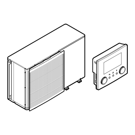
Operation 5 Operation INFORMATION Heating is only applicable in case of reversible models. 5.1 User interface: Overview The user interface has the following components: a Slot for WLAN cartridge b USB connector c LCD screen d Dials and buttons Slot for WLAN cartridge With the WLAN cartridge, the installer can connect the system to the internet. - Page 16 Operation Item Description Left dial The LCD shows an arc on the left side of the display when you can use the left dial. ▪ : Turn, then press the left dial. Navigate through the menu structure. ▪ : Turn the left dial. Choose a menu item. ▪...
-
Page 17: Menu Structure: Overview User Settings
Operation 5.2 Menu structure: Overview user settings Room Schedule Heating schedule Cooling schedule Antifrost [1.4] Antifrost Setpoint range Room sensor offset Activation Room comfort setpoint Room setpoint [1.5] Setpoint range Heating minimum Main zone Heating maximum Cooling minimum Schedule Cooling maximum Heating schedule Cooling schedule [1.9]... -
Page 18: Possible Screens: Overview
Operation 5.3 Possible screens: Overview The most common screens are as follows: – a Home screen b Main menu screen c Lower level screens: c1: Setpoint screen c2: Detailed screen with values c3: Screen with weather-dependent curve c4: Screen with schedule 5.3.1 Home screen Press the button to go back to the home screen. - Page 19 Operation Item Description Emergency Heat pump failure and system operates in Emergency mode or heat pump is forced off. Current date and time Smart energy Smart energy is available via solar panels or smart grid. Smart energy is currently being used for space heating. Space operation mode Cooling Heating...
-
Page 20: Main Menu Screen
Operation Item Description Additional zone h1 Installed room thermostat type: Unit operation is decided by the external room thermostat (wired or wireless). — No room thermostat installed or set. Unit operation is decided based on the leaving water temperature regardless of the actual room temperature and/or heating demand of the room. -
Page 21: Setpoint Screen
Operation Submenu Description Restriction: Only displayed if a dedicated Room Human Comfort Interface (BRC1HHDA used as room thermostat) is controlling the outdoor unit. Set the room temperature. Main zone Shows the applicable symbol for your main zone emitter type. Set the leaving water temperature for the main zone. -
Page 22: Detailed Screen With Values
Operation Examples [1] Room temperature screen [2] Main zone screen °C °C – – Room Main zone [3] Additional zone screen °C – Additional zone Explanation – Possible actions on this screen Go through the list of the submenu. Go to the submenu. Adjust and automatically apply the desired temperature. -
Page 23: Turning Operation On Or Off
Operation c Selected setting and value Possible actions on this screen Go through the list of settings. Change the value. Go to the next setting. Confirm changes and proceed. 5.4 Turning operation ON or OFF 5.4.1 Visual indication Certain functionalities of the unit can be enabled or disabled separately. If a functionality is disabled, the corresponding temperature icon in the home screen will be greyed out. -
Page 24: Reading Out Information
Operation 5.5 Reading out information To read out information 1 Go to [8]: Information. Possible read-out information In menu… You can read out… [8.1] Energy data Produced energy, consumed electricity, and consumed gas [8.2] Malfunction history Malfunction history [8.3] Dealer information Contact/helpdesk number [8.4] Sensors Room temperature, outside... - Page 25 Operation ▪ If your unit is a heating/cooling model, it can both heat up and cool down a space. You have to tell the system which operation mode to use. To determine if a heating/cooling heat pump model is installed 1 Go to [4]: Space heating/cooling.
-
Page 26: Determining Which Temperature Control You Are Using
Operation ▪ When the unit is not in operation, the status indicator will show a blue pulsation with an interval of approximately 5 seconds. ▪ While the unit is in operation, the status indicator will light up blue constantly. To set the space operation mode 1 Go to [4.1]: Space heating/cooling >... -
Page 27: To Change The Desired Room Temperature
Operation 26 Jun 2020 18:19 a1 Heat emitter of the main zone (in this example Underfloor heating) a2 Heat emitter of the additional zone (in this example Fancoil unit). If no icon is displayed, there is no additional zone. b Room thermostat type of the main zone: If b=…... -
Page 28: To Change The Desired Leaving Water Temperature
Operation 2 Select No. 5.6.5 To change the desired leaving water temperature INFORMATION The leaving water is the water that is sent to the heat emitters. The desired leaving water temperature is set by your installer in accordance with the heat emitter type. Only adjust the leaving water temperature settings in case of problems. -
Page 29: Preset Values And Schedules
Operation 2 Select No. To enable weather-dependent operation for the leaving water temperature "5.8.4 Using weather-dependent curves" [ 41]. 5.7 Preset values and schedules 5.7.1 Using preset values About preset values For some settings in the system, you can define preset values. You only need to set these values one time, then reuse the values in other screens such as the scheduling screen. - Page 30 Operation You can… See… Consult which schedule is currently "Schedule/Control" in "Possible selected. schedules" [ 30] Select another schedule if needed. "To select which schedule you currently want to use" [ 30] Program your own schedules if the ▪ "Possible actions" in "Possible predefined schedules are not satisfactory.
- Page 31 Operation Schedule/Control Description [1.2] Room > Heating Predefined schedules: 3 schedule Activation screen: [1.1] Schedule Schedule for the desired room Possible actions: Temperatures within range. temperature in heating mode. [1.3] Room > Cooling Predefined schedules: 1 schedule Activation screen: [1.1] Schedule Schedule for the desired room Possible actions: Temperatures within range.
-
Page 32: Schedule Screen: Example
Operation Schedule/Control Description [7.4.2] User settings > Predefined schedules: 1 Quiet > Schedule Activation screen: [7.4.1] Activation (only Schedule for when the unit has available to installers). to use which quiet mode level. Possible actions: You can use the following system-defined preset values: ▪... - Page 33 Operation To go to the schedule 1 Go to [1.1]: Room > Schedule. 2 Set scheduling to Yes. 3 Go to [1.3]: Room > Cooling schedule To clear the content of the week schedule 1 Select the name of the current schedule. User defined 1 2 Select Delete.
- Page 34 Operation 2 Select Edit. Delete Edit Copy 3 Use the left dial to select an entry and edit the entry with the right dial. You can program up to 6 actions each day. On the bar, a high temperature has a darker colour than a low temperature.
- Page 35 Operation 4 Select Paste. Delete Edit Copy Paste Result: User defined 1 5 Repeat this action for all other weekdays. — User defined 1 To program the schedule for Saturday and copy it to Sunday 1 Select Saturday. 2 Select Edit. 3 Use the left dial to select an entry and edit the entry with the right dial.
-
Page 36: Setting The Energy Prices
Operation To rename the schedule 1 Select the name of the current schedule. User defined 1 2 Select Rename. Delete Rename Select 3 (optional) To delete the current schedule name, browse through the character list until ← is displayed, then press to remove the previous character. - Page 37 Operation INFORMATION Price value ranging from 0.00~990 valuta/kWh (with 2 significant values). To set the electricity price 1 Go to [7.5.1]/[7.5.2]/[7.5.3]: User settings > Electricity price > High/Medium/Low. 2 Select the correct electricity price. 3 Confirm the changes. 4 Repeat this for all three electricity prices. —...
-
Page 38: Weather-Dependent Curve
Operation For the procedure to set the electricity price, see "To set the electricity price" [ 37]. Example This is an example and the prices and/or values used in this example are NOT accurate. Data Price/kWh Gas price 4.08 Electricity price 12.49 Renewable heat incentive per kWh Calculation of the gas price... -
Page 39: 2-Points Curve
Operation ▪ 2-points curve ▪ Slope-offset curve Which type of curve you use to make adjustments, depends on your personal preference. See "5.8.4 Using weather-dependent curves" [ 41]. Availability The weather-dependent curve is available for: ▪ Main zone - Heating ▪ Main zone - Cooling ▪... -
Page 40: Slope-Offset Curve
Operation 5.8.3 Slope-offset curve Slope and offset Define the weather-dependent curve by its slope and offset: ▪ Change the slope to differently increase or decrease the temperature of the leaving water for different ambient temperatures. For example, if leaving water temperature is in general fine but at low ambient temperatures too cold, raise the slope so that leaving water temperature is heated increasingly more at decreasingly lower ambient temperatures. -
Page 41: Using Weather-Dependent Curves
Operation Item Description Y1, Y2, Y3, Examples of desired leaving water temperature. The icon corresponds to the heat emitter for that zone: ▪ : Underfloor heating ▪ : Fan coil unit ▪ : Radiator Possible actions on this screen Select slope or offset. Increase or decrease the slope/offset. - Page 42 Operation Zone Go to … Additional zone – Heating [3.5] Additional zone > Heating WD curve Additional zone – Cooling [3.6] Additional zone > Cooling WD curve INFORMATION Maximum and minimum setpoints You cannot configure the curve with temperatures that are higher or lower than the set maximum and minimum setpoints for that zone.
-
Page 43: Other Functionalities
Operation 5.9 Other functionalities 5.9.1 To configure time and date 1 Go to [7.2] User settings > Time/date. 5.9.2 Using quiet mode About quiet mode You can use quiet mode to decrease the sound of the outdoor unit. However, this also decreases the heating/cooling capacity of the system. -
Page 44: Using Wlan
Operation Typical workflow Using holiday mode typically consists of the following stages: Activating the holiday mode. Setting the starting date and ending date of your holiday. To check if holiday mode is activated and/or running is displayed on the home screen, holiday mode is active. To configure the holiday 1 Activate the holiday mode. - Page 45 Operation WLAN cartridge The WLAN cartridge needs to be inserted in the user interface. Router Field supply. Smartphone + app The ONECTA app needs to be installed on the user's smartphone. See: http://www.onlinecontroller.daikineurope.com/ Configuration To configure the ONECTA app, follow the in-app instructions. While doing this, the following actions and information are needed on the user interface: [D] Wireless gateway User profile...
- Page 46 Operation 2 Read out the connection status: ▪ Disconnected from [WLAN_SSID] ▪ Connected to [WLAN_SSID] [D.6] Cloud connection: Read out the status of the connection to the cloud: 1 Go to [D.6]: Wireless gateway > Cloud connection. 2 Read out the connection status: ▪...
-
Page 47: Energy Saving Tips
Energy saving tips 6 Energy saving tips Tips about room temperature ▪ Make sure the desired room temperature is NEVER too high (in heating mode) or too low (in cooling mode), but ALWAYS according to your actual needs. Each saved degree can save up to 6% of heating/cooling costs. ▪... -
Page 48: Maintenance And Service
Maintenance and service 7 Maintenance and service 7.1 Overview: Maintenance and service The installer has to perform a yearly maintenance. You can find the contact/ helpdesk number via the user interface. 1 Go to [8.3]: Information > Dealer information. As end user, you have to: ▪... - Page 49 Maintenance and service NOTICE Applicable legislation on fluorinated greenhouse gases requires that the refrigerant charge of the unit is indicated both in weight and CO equivalent. Formula to calculate the quantity in CO equivalent tonnes: GWP value of the refrigerant × total refrigerant charge [in kg]/1000 Contact your installer for more information.
-
Page 50: Troubleshooting
Troubleshooting 8 Troubleshooting Contact For the symptoms listed below, you can try to solve the problem yourself. For any other problem, contact your installer. You can find the contact/helpdesk number via the user interface. 1 Go to [8.3]: Information > Dealer information. 8.1 To display the help text in case of a malfunction In case of a malfunction, the following will appear on the home screen depending on the severity:... -
Page 51: Symptom: You Are Feeling Too Cold (Hot) In Your Living Room
Troubleshooting 8.3 Symptom: You are feeling too cold (hot) in your living room Possible cause Corrective action The desired room temperature is too Increase (decrease) the desired room low (high). temperature. See "5.6.4 To change the desired room temperature" [ 27]. If the problem recurs daily, do one of the following: ▪... -
Page 52: Symptom: The System Is Making Gurgling Noises After Commissioning
Troubleshooting Possible cause Corrective action Unit is damaged. "8.1 To display the help text in case of a malfunction" [ 50]. INFORMATION When the backup heater takes over the heat load, electricity consumption will be considerably higher. 8.5 Symptom: The system is making gurgling noises after commissioning Possible cause Corrective action There is air in the system. -
Page 53: Relocation
Relocation 9 Relocation 9.1 Overview: Relocation If you want to relocate parts of your system, contact your installer. You can find the contact/helpdesk number via the user interface. 1 Go to [8.3]: Information > Dealer information. EWAA011~016DA + EWYA009~016DA User reference guide Packaged air-cooled water chillers and packaged air to water heat pumps 4P620246-1B –... -
Page 54: Disposal
Disposal 10 Disposal NOTICE Do NOT try to dismantle the system yourself: dismantling of the system, treatment of the refrigerant, oil and other parts MUST comply with applicable legislation. Units MUST be treated at a specialised treatment facility for reuse, recycling and recovery. EWAA011~016DA + EWYA009~016DA User reference guide Packaged air-cooled water chillers... -
Page 55: Glossary
Optional equipment Equipment made or approved by Daikin that can be combined with the product according to the instructions in the accompanying documentation. Field supply Equipment NOT made by Daikin that can be combined with the product according to the instructions in the accompanying documentation. -
Page 56: Installer Settings: Tables To Be Filled In By Installer
Installer settings: Tables to be filled in by installer 12 Installer settings: Tables to be filled in by installer 12.1 Configuration wizard Setting Fill in… System Backup heater type [9.3.1] Emergency [9.5] Number of zones [4.4] Glycol Filled system (overview field setting [E‑0D]) Backup heater Voltage [9.3.2]... - Page 57 Installer settings: Tables to be filled in by installer Setting Fill in… Information Dealer information [8.3] EWAA011~016DA + EWYA009~016DA User reference guide Packaged air-cooled water chillers and packaged air to water heat pumps 4P620246-1B – 2023.11...
- Page 60 4P620246-1B 2023.11...
Need help?
Do you have a question about the EWAA0116DAW1P and is the answer not in the manual?
Questions and answers