Table of Contents
Advertisement
Quick Links
OEX
OWNER'S MANUAL
#4700 #4800 #4900
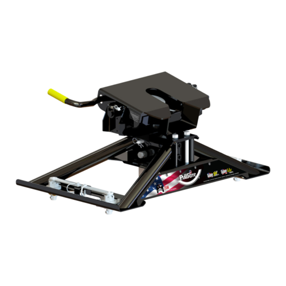
OEX Series Fifth Wheel Hitch (25K)
#4700 for 2010 to present model Ford trucks
#4800 for 2013 to present model Ram trucks
#4900 for 2020 to present model GM trucks
Gross Trailer Weight (Maximum) .......... 25,000 lbs.
Vertical Load Weight (Max. Pin Weight)...6,000 lbs.
The following instructions provide valuable information regarding the function and proper use of the Super 5th OEX Towing System.
.
YOU MUST COMPLETELY READ THE INSTRUCTIONS WITHIN THIS MANUAL, PRIOR TO OPERATING THE HITCH TO PREVENT UNNECESSARY DAMAGE
TO THE HITCH, VEHICLE, OR TRAILER.
For more information, please call PullRite at (800) 443-2307.
2.7.24 Rev B RH
Advertisement
Table of Contents

Related Manuals for PullRite Super 5th OEX Series


Summary of Contents for PullRite Super 5th OEX Series
- Page 1 The following instructions provide valuable information regarding the function and proper use of the Super 5th OEX Towing System. YOU MUST COMPLETELY READ THE INSTRUCTIONS WITHIN THIS MANUAL, PRIOR TO OPERATING THE HITCH TO PREVENT UNNECESSARY DAMAGE TO THE HITCH, VEHICLE, OR TRAILER. For more information, please call PullRite at (800) 443-2307. 2.7.24 Rev B RH...
-
Page 2: Table Of Contents
TABLE OF CONTENTS SYSTEM WEIGHT RATING VS. COMPONENT WEIGHT RATING............3 CAB CLEARANCE............................3 BASE MODELS.............................4 SUPER 5TH COUPLER KIT..........................5 FIFTH WHEEL PLATE OPERATION......................6,7 LUBRICATION / ANNUAL MAINTANANCE....................8 ATTACHING ROCKER ARM TO COLUMN....................9 FRONT TO BACK COLUMN ADJUSTMENTS..................10,11 HEIGHT ADJUSTMENT..........................12 HITCH INSTALLATION...........................13,14 MOUNTING POST ADJUSTMENTS......................14 HITCHING..............................15 SAFETY CHECKS PRIOR TO TOWING.....................15... -
Page 3: System Weight Rating Vs. Component Weight Rating
Depending on the hitch plate install location, the offset could move the king pin behind the truck's rear axle. While the Super 5th OEX can be used with these shorter bed trucks, keep in mind that PullRite only recommends the use of a SuperGlide slider hitch for any towing application without 100% cab clearance. -
Page 4: Base Models
BASE MODELS The Super 5th OEX is available for Ford, Ram, and GM trucks with OE hitch mounting system (years listed below). NOTE: This manual uses the #4800 as an example for instruction, however all bases listed below are similar in function. #4700 for FORD 2010-Present Hitch Base #4730 Super 5th coupler kit #4820... -
Page 5: Super 5Th Coupler Kit
SUPER 5TH COUPLER KIT #4820 All bases model hitches with the Super 5th OEX coupling method use the same hardware kit as shown below. Super 5th OEX coupler kit #4820 HEAD PLATE ASSEMBLY 3601 # 9 PIN CLIP 98410143 5/8" DIA. X 4" HITCH PIN 010019 5/8”-11 X 2"... -
Page 6: Fifth Wheel Plate Operation
FIFTH WHEEL PLATE OPERATION A better understanding of the plate locking and unlocking operation can be obtained by viewing the working parts from the underside of the plate. The Fifth Wheel Plate can be removed and turned over to view the workings of the mechanism. - Page 7 FIFTH WHEEL PLATE OPERATION CAUTION: DO NOT ATTEMPT TO TRIP THE LOCK MECHANISM WITH YOUR HAND. USE A PROBE DEVICE TO SIMULATE THE KING PIN ACTION. CLOSED LIFT UPWARD AND PULL OUT WITH FORCE UNTIL LOCK CATCH ENGAGES OPEN CLOSED OPEN 2.7.24 Rev B RH...
-
Page 8: Lubrication / Annual Maintanance
DO NOT OPERATE HITCH UNTIL YOU READ THIS SECTION! HEAD PLATE ASSEMBLY The Head Plate must be lubricated before each trip or as need- ed. PullRite recommends using a light lubricant spray such as WD-40 or 3-IN-ONE Oil to prevent the attraction of dust and debris. -
Page 9: Attaching Rocker Arm To Column
ATTACHING ROCKER ARM TO COLUMN The Head Plate sits on the Rocker Arm. Attach the Rocker Arm to the Column by following the steps below. 1. Apply a light coat of general purpose grease to the Pivot Bolt shaft and set it aside. 2. -
Page 10: Front To Back Column Adjustments
FRONT TO BACK COLUMN ADJUSTMENT All Super 5th OEX hitches are adjustable front to back and can place the head plate behind the axle, allowing 4" of rear- ward offset. The OEX forward position is in Figure 1, but if you find the best position for towing is with the head plate closer to the tailgate (Fig. - Page 11 FRONT TO BACK COLUMN ADJUSTMENT 6. Remove the (4) 5/8" X 6" hex bolts holding the Column Plates (Fig. 6) 7. Turn the top and bottom plates to the rearward position (Fig. 7). 8. Replace the (4) 5/8" X 6" hex bolts and set the coulmn through both plates in the rearward position. Place column hitch pin through the height adjustment hole into desired height position.
-
Page 12: Height Adjustment
HEIGHT ADJUSTMENT The Super 5th OEX is height adjustable and can be set in three positions. Refer to the illustration below, following each step below to adjust your hitch’s height: 1. Loosen the two Rocker Arm Column jam nuts as well as the two bolts on the passenger side and driver side. It is not necessary to remove the bolts, just back out about two complete turns or until the column is loose in the base. -
Page 13: Hitch Installation
HITCH INSTALLATION Place the OEX post holes directly over the pucks. The hitch head opening should be facing the tailgate. You will be able to adjust OEX foot plates so that each Mounting Post drops into place as you go around the hitch. 1. -
Page 14: Mounting Post Adjustments
HITCH INSTALLATION 4. Rotate handles 90º (Fig. 4), posts may need to be adjusted as explained below in MOUNTING POST ADJUSTMENTS. 5. After Inserting and locking all posts (Fig. 4), tighten the adjustment plates on the OEX feet to 13 foot pounds. 6. -
Page 15: Hitching
HITCHING WARNING: Never perform any of the following actions while any part of a person is between the vehicle and trailer. 1. Align your truck with the center of the trailer. The truck should be close to parallel to the centerline of the trailer. 2. -
Page 16: Unhitching / Challenge Vs Solution
I need to have a professional evaluate my Contact PullRite’s Customer Service Dept. at (800) 443-2307. Super 5th OEX. Your needs will be assessed and resolved by PullRite or you will be directed to an authorized PullRite Service Center. 2.7.24 Rev B RH... -
Page 17: Torque Table
TORQUE TABLE Apply these torque specifications for the corresponding items listed below upon installation and subsequent inspections of the Super 5th OEX. See parts list for identification of items listed on this table. HARDWARE SIZE TORQUE SPECS 45 FT. LBS. - FOUR BOLTS THROUGH COLUMN COLUMN PLATE SCREWS 5/8”... -
Page 18: 4700 Exploded View / Parts List
SUPERLITE OEX # 4700 EXPLODED VIEW MOUNTING POST ASSEMBLY* TAILGATE SIDE 2.7.24 Rev B RH... - Page 19 #4700 PARTS LIST NAME PART NO DESCRIPTION HITCH PLATE ASSEMBLY 3601 ROCKER ARM 4821 FORD OEX HITCH BASE 4730 OEX DS FRONT MOUNTING POST KIT 47341 OEX REAR MOUNTING POST KIT 47343 OEX PS FRONT MOUNTING POST KIT 47342 SUPER 5TH COUPLER KIT # 4820 ( INCLUDES HITCH PLATE ) HITCH PIN CLIP 98410127 #3 13 GAUGE 1.63"...
-
Page 20: 4800 Exploded View / Parts List
SUPERLITE OEX # 4800 EXPLODED VIEW MOUNTING POST ASSEMBLY* TAILGATE SIDE 2.7.24 Rev B RH... - Page 21 #4800 PARTS LIST NAME PART NO DESCRIPTION HITCH PLATE ASSEMBLY 3601 ROCKER ARM 4821 RAM OEX HITCH BASE 4830 OEX DS FRONT MOUNTING POST 48341 OEX REAR MOUNTING POSTS 48343 OEX PS FRONT MOUNTING POST 48342 SUPER 5TH COUPLER KIT # 4820 ( INCLUDES HITCH PLATE ) HITCH PIN CLIP 98410127 #3 13 GAUGE 1.63"...
-
Page 22: 4900 Exploded View / Parts List
SUPERLITE OEX # 4900 EXPLODED VIEW MOUNTING POST ASSEMBLY* TAILGATE SIDE 2.7.24 Rev B RH... - Page 23 #4900 PARTS LIST NAME PART NO DESCRIPTION HITCH PLATE ASSEMBLY 3601 ROCKER ARM 4821 GM OEX HITCH BASE 4730 OEX DS FRONT MOUNTING POST KIT 49341 OEX REAR MOUNTING POST KIT 49343 OEX PS FRONT MOUNTING POST KIT 49342 SUPER 5TH COUPLER KIT # 4820 ( INCLUDES HITCH PLATE ) HITCH PIN CLIP 98410127 #3 13 GAUGE 1.63"...
-
Page 24: Year Limited Warranty
PULLIAM immediately, either in writing or by telephone call, Attention Customer Service Department. The owner will be instructed to return the hitch at his expense either to an authorized PullRite dealer or to PULLIAM to repair or replace any parts necessary to correct defects in material or workmanship. - Page 25 Product Warranty Registration As an owner of a PullRite product, you must register your product to be considered for warranty coverage. See Owners Manual for further details. Please note, that you can also register online at www.pullrite.com/warranty.htm. Name: ___________________________________________________________________________________ Address: _________________________________________________________________________________...
- Page 26 MANUFACTURED BY: PULLIAM ENTERPRISES, INC. 13790 East Jefferson Blvd. Mishawaka, IN 46545 (574) 259-1520 • (800) 443-2307 info@pullrite.com • www.pullrite.com...
Need help?
Do you have a question about the Super 5th OEX Series and is the answer not in the manual?
Questions and answers