Table of Contents
Advertisement
Quick Links
www.ti.com
EVM User's Guide: LAUNCHXL-F28P55X
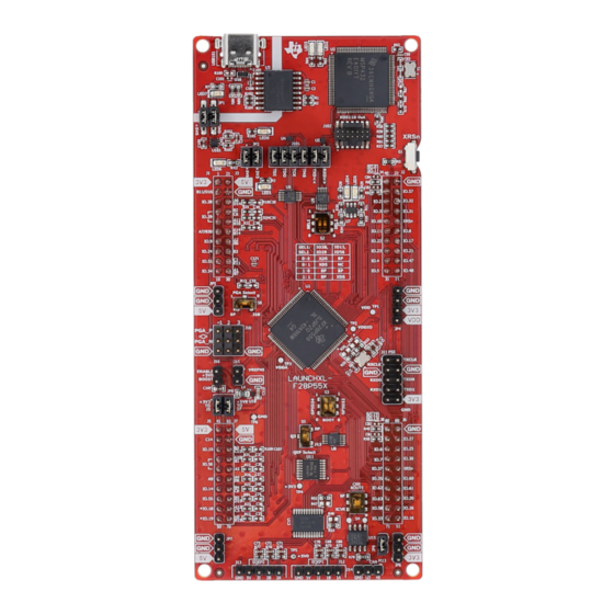
C2000 F28P55x Series LaunchPad Development Kit
Description
The LAUNCHXL-F28P55X is a low-cost development
board for the Texas Instruments C2000
Time Microcontroller series of F28P55x devices.
The LAUNCHXL-F28P55X is designed around the
TMS320F28P550SJ9 real-time MCU and highlights
the control, analog, and communications peripherals,
as well as the integrated nonvolatile memory.
The LaunchPad
™
also features two independent
BoosterPack
™
XL expansion connectors (80-pins),
on-board Controller Area Network (CAN) transceiver
supporting CAN-FD (MCAN), two 5 V encoder
interface (eQEP) connectors, FSI connector, three
PGA interface connectors, power-domain isolation,
and an on-board XDS110 debug probe.
Get Started
1. Order LAUNCHXL-F28P55X from ti.com.
2. Download the latest libraries.
3. Download the comprehensive reference design
files.
4. See the latest device support files.
Features
•
C2000 Series F28P550SJ9PZ (100-pin)
microcontroller:
– With Configurable Logic Block (CLB) capability
SPRUJC0 – APRIL 2024
Submit Document Feedback
•
On-board XDS110 debug probe
•
Two user-controlled LEDs
•
One microcontroller reset switch
™
Real-
•
Selectable power domains:
– USB (isolated)
– BoosterPack
– External power supply
•
CAN connector with on-board CAN transceiver
– Supports CAN-FD (MCAN)
•
Two independent Enhanced Quadrature Encoder
Pulse (QEP)-based encoder connectors
•
Three Programmable Gain Amplifier (PGA)-based
connectors
•
FSI peripheral connector
•
Two independent BoosterPack XL standard
connectors (80-pins) featuring stackable headers
to maximize expansion through the BoosterPack
ecosystem
Applications
•
Motor drives
•
Appliances
•
Hybrid, electric and powertrain systems
•
Solar and EV charging
•
Digital power
•
Body electronics and lighting
•
Test and measurement
Copyright © 2024 Texas Instruments Incorporated
C2000 F28P55x Series LaunchPad Development Kit
Description
1
Advertisement
Table of Contents

Subscribe to Our Youtube Channel
Related Manuals for Texas Instruments C2000 F28P55 Series


Summary of Contents for Texas Instruments C2000 F28P55 Series
- Page 1 On-board XDS110 debug probe Description • Two user-controlled LEDs The LAUNCHXL-F28P55X is a low-cost development • One microcontroller reset switch board for the Texas Instruments C2000 ™ Real- • Selectable power domains: Time Microcontroller series of F28P55x devices. – USB (isolated) The LAUNCHXL-F28P55X is designed around the –...
-
Page 2: Kit Contents
1 Evaluation Module Overview 1.1 Introduction The F28P55x LaunchPad (LAUNCHXL-28P55X) from Texas Instruments (TI) provides a great way to learn and experiment with the F28P55x devices. The F28P55x device is a member of TI’s C2000 family of microcontrollers (MCUs). This 100-pin LaunchPad is intended to provide a well-filtered, robust design capable of working in most environments. -
Page 3: Device Information
For details on the demo program of the LaunchPad, see Section 3.1.2. SPRUJC0 – APRIL 2024 C2000 F28P55x Series LaunchPad Development Kit Submit Document Feedback Copyright © 2024 Texas Instruments Incorporated... - Page 4 PWR & GND Isola o n Boundary ¡ 3.3V & 5V Isola on Boundary Figure 2-1. F28P55x LaunchPad Development Kit Block Diagram C2000 F28P55x Series LaunchPad Development Kit SPRUJC0 – APRIL 2024 Submit Document Feedback Copyright © 2024 Texas Instruments Incorporated...
-
Page 5: Power Domains
Figure 2-2. LaunchPad Power Distribution Diagram Isola o n Boundary ¡ 3.3V & 5V Isola on Boundary Figure 2-3. LaunchPad Power Plane Diagram SPRUJC0 – APRIL 2024 C2000 F28P55x Series LaunchPad Development Kit Submit Document Feedback Copyright © 2024 Texas Instruments Incorporated... -
Page 6: Encoder Connectors
The LAUNCHXL-F28P55X does not include any on-board isolation devices for the FSI signals. If interested in evaluating the FSI peripheral with isolation devices, or differential drivers and receivers, then see the TMDSFSIADAPEVM plug on board. C2000 F28P55x Series LaunchPad Development Kit SPRUJC0 – APRIL 2024 Submit Document Feedback Copyright © 2024 Texas Instruments Incorporated... - Page 7 GPIO24 (LEFT) GPIO32 (RIGHT) Boot from parallel GPIO Boot from SCI / wait boot Boot from CAN Boot from flash (default) SPRUJC0 – APRIL 2024 C2000 F28P55x Series LaunchPad Development Kit Submit Document Feedback Copyright © 2024 Texas Instruments Incorporated...
- Page 8 JP8 and there is no contention between the two BoosterPacks. C2000 F28P55x Series LaunchPad Development Kit SPRUJC0 – APRIL 2024 Submit Document Feedback Copyright © 2024 Texas Instruments Incorporated...
- Page 9 COM port. When UART functionality is not needed at the virtual COM port, the GPIOs can be routed to the BoosterPack connectors for BoosterPack standard functions. SPRUJC0 – APRIL 2024 C2000 F28P55x Series LaunchPad Development Kit Submit Document Feedback Copyright © 2024 Texas Instruments Incorporated...
- Page 10 FSI header are made short to verify higher signal integrity, as FSI signals can switch at frequencies up to 150MHz on F28P55x devices. C2000 F28P55x Series LaunchPad Development Kit SPRUJC0 – APRIL 2024 Submit Document Feedback Copyright © 2024 Texas Instruments Incorporated...
- Page 11 The LaunchPad also functions as a foundation for expansion with custom BoosterPacks and other circuits. This document can serve as a starting point for such projects. SPRUJC0 – APRIL 2024 C2000 F28P55x Series LaunchPad Development Kit Submit Document Feedback Copyright © 2024 Texas Instruments Incorporated...
- Page 12 BoosterPacks are pluggable add-on boards for the LaunchPad ecosystem that follow a pin-out standard created by Texas Instruments. The TI and third-party ecosystem of BoosterPacks greatly expands the peripherals and potential applications that you can explore with the F28P55x LaunchPad.
-
Page 13: Hardware Revisions
LaunchPad. To do this in Windows open the Device Manager. Look for an entry under Ports (COM and LPT) titled XDS110 Class Application/User UART (COMX), where X is a number. Remember this number for opening a serial terminal. SPRUJC0 – APRIL 2024 C2000 F28P55x Series LaunchPad Development Kit Submit Document Feedback Copyright © 2024 Texas Instruments Incorporated... - Page 14 Using a jumper wire connect the ADCINA6 header to a 3.3V, GND, or other 0-3.3V signal to see the on-screen value change. Figure 3-3. LaunchPad Demo Serial Terminal - ADC Sampling C2000 F28P55x Series LaunchPad Development Kit SPRUJC0 – APRIL 2024 Submit Document Feedback Copyright © 2024 Texas Instruments Incorporated...
- Page 15 10. Click Load Program and select the binary of the program to load. The binary is loaded onto the device and can now be run and debugged. SPRUJC0 – APRIL 2024 C2000 F28P55x Series LaunchPad Development Kit Submit Document Feedback Copyright © 2024 Texas Instruments Incorporated...
- Page 16 The layout source files for the LAUNCHXL-F28P55X are included in the LAUNCHXL-F28P55X design files download. Figure 4-2. GND - Layer 2 Figure 4-1. Top Signal - Layer 1 C2000 F28P55x Series LaunchPad Development Kit SPRUJC0 – APRIL 2024 Submit Document Feedback Copyright © 2024 Texas Instruments Incorporated...
- Page 17 F28P55x LaunchPad that shows the location of selected features of the board as well as the component locations. Figure 4-5. F28P55x LaunchPad Dimensions and Component Locations SPRUJC0 – APRIL 2024 C2000 F28P55x Series LaunchPad Development Kit Submit Document Feedback Copyright © 2024 Texas Instruments Incorporated...
-
Page 18: Bill Of Materials (Bom)
Target Scan Format as OSCAN2 format. Alternately, a working Target configuration file is included in the launcxl_ex1_F28P55X_demo project TMS320F28P55X_LaunchPad.ccxml. Users can use this without modifications. Figure 5-1. Target Configuration Advanced Options C2000 F28P55x Series LaunchPad Development Kit SPRUJC0 – APRIL 2024 Submit Document Feedback Copyright © 2024 Texas Instruments Incorporated... - Page 19 Application Specific Designs & Evaluation with C2000 Real-Time Microcontrollers • C2000WARE Quick Start Guide • Texas Instruments Code Composer Studio • Texas Instruments LaunchPad Development Environment SPRUJC0 – APRIL 2024 C2000 F28P55x Series LaunchPad Development Kit Submit Document Feedback Copyright © 2024 Texas Instruments Incorporated...
- Page 20 TPS7A37 1A, High-Accuracy, Ultra-Low-Dropout Voltage Regulator with Reverse Current Protection and Enable • SN74LVC8T245 8-Bit Dual-Supply Bus Transceiver with Configurable Voltage-Level Shifting and Three-State Outputs C2000 F28P55x Series LaunchPad Development Kit SPRUJC0 – APRIL 2024 Submit Document Feedback Copyright © 2024 Texas Instruments Incorporated...
- Page 21 STANDARD TERMS FOR EVALUATION MODULES Delivery: TI delivers TI evaluation boards, kits, or modules, including any accompanying demonstration software, components, and/or documentation which may be provided together or separately (collectively, an “EVM” or “EVMs”) to the User (“User”) in accordance with the terms set forth herein.
- Page 22 www.ti.com Regulatory Notices: 3.1 United States 3.1.1 Notice applicable to EVMs not FCC-Approved: FCC NOTICE: This kit is designed to allow product developers to evaluate electronic components, circuitry, or software associated with the kit to determine whether to incorporate such items in a finished product and software developers to write software applications for use with the end product.
- Page 23 www.ti.com Concernant les EVMs avec antennes détachables Conformément à la réglementation d'Industrie Canada, le présent émetteur radio peut fonctionner avec une antenne d'un type et d'un gain maximal (ou inférieur) approuvé pour l'émetteur par Industrie Canada. Dans le but de réduire les risques de brouillage radioélectrique à...
- Page 24 www.ti.com EVM Use Restrictions and Warnings: 4.1 EVMS ARE NOT FOR USE IN FUNCTIONAL SAFETY AND/OR SAFETY CRITICAL EVALUATIONS, INCLUDING BUT NOT LIMITED TO EVALUATIONS OF LIFE SUPPORT APPLICATIONS. 4.2 User must read and apply the user guide and other available documentation provided by TI regarding the EVM prior to handling or using the EVM, including without limitation any warning or restriction notices.
- Page 25 Notwithstanding the foregoing, any judgment may be enforced in any United States or foreign court, and TI may seek injunctive relief in any United States or foreign court. Mailing Address: Texas Instruments, Post Office Box 655303, Dallas, Texas 75265 Copyright © 2023, Texas Instruments Incorporated...
- Page 26 TI products. TI’s provision of these resources does not expand or otherwise alter TI’s applicable warranties or warranty disclaimers for TI products. TI objects to and rejects any additional or different terms you may have proposed. IMPORTANT NOTICE Mailing Address: Texas Instruments, Post Office Box 655303, Dallas, Texas 75265 Copyright © 2024, Texas Instruments Incorporated...
Need help?
Do you have a question about the C2000 F28P55 Series and is the answer not in the manual?
Questions and answers