Texas Instruments CC3200 User Manual
Hide thumbs
Also See for CC3200:
- Technical reference manual (572 pages) ,
- Programmer's manual (73 pages) ,
- User manual (29 pages)

Related Manuals for Texas Instruments CC3200


Summary of Contents for Texas Instruments CC3200
- Page 1 ® CC3200 SimpleLink™ Wi-Fi and Internet of Things Solution With MCU LaunchPad™ Hardware User's Guide Literature Number: SWRU372C June 2014 – Revised March 2020...
-
Page 2: Table Of Contents
The CC3200 Code Examples .................... CC3200 Application Notes ..................... Support Resources ......................Known Limitations ....................Hardware Limitations .......................... Revision History Table of Contents SWRU372C – June 2014 – Revised March 2020 Submit Documentation Feedback Copyright © 2014–2020, Texas Instruments Incorporated... - Page 3 List of Figures ................ CC3200 LaunchPad Development Kit Overview ..................... CC3200 Block Diagram ..............Pn-1 Marking on the LaunchPad Kit (White Triangle) ....................... JTAG Headers ......................C Connections ....................... UART Signals ....................... SOP Jumpers ......................2x20 Pin Connector .......................
-
Page 4: Introduction
The LaunchPad kit design highlights the CC3200 Internet-on-a-chip™ solution and Wi-Fi capabilities. The CC3200 LaunchPad kit also features programmable user buttons, RGB LED for custom applications, and onboard emulation for debugging. The stackable headers of the CC3200 LaunchPad XL interface demonstrate how easy it is to expand the functionality of the LaunchPad kit when interfacing with other peripherals on many existing BoosterPack™... -
Page 5: What's Included
• Quick start guide FCC/IC Regulatory Compliance The CC3200 SimpleLink Wi-Fi and IoT solution with MCU LaunchPad kit hardware is FCC Part 15 and IC ICES-003 Class A compliant. Trademarks LaunchPad, Internet-on-a-chip, BoosterPack, Code Composer Studio, E2E are trademarks of Texas Instruments. -
Page 6: Hardware Description
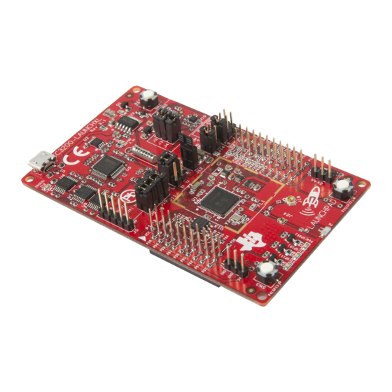
Hardware Description www.ti.com Hardware Description Figure 1. CC3200 LaunchPad Development Kit Overview Block Diagram Figure 2. CC3200 Block Diagram ® SWRU372C – June 2014 – Revised March 2020 CC3200 SimpleLink™ Wi-Fi and Internet of Things Solution With MCU LaunchPad™ Hardware Submit Documentation Feedback Copyright ©... -
Page 7: Hardware Features
Note that the connectors do not have a key to prevent the misalignment of the pins or reverse connection. Ensure that VCC and 5V pins are aligned with the BoosterPack module header pins. On the CC3200 LaunchPad kit, a small white triangle symbol is provided near Pin-1 (see Figure 3) to orient all BoosterPack modules. -
Page 8: Jumpers, Switches, And Leds
2.4.1 JTAG Headers The headers are provided on the board to isolate the CC3200 device from the mounted FTDI JTAG emulator. These jumpers are shorted by default when the board is shipped from TI. To connect an external emulator, remove these jumpers and place the external emulator on the pins closer to the CC3200 device. -
Page 9: Jumper Settings
The board can be powered by using the on-board micro USB connector. An on-board LDO provides 3.3 V for the CC3200 and the rest of the board to operate. This supply can be isolated from the LDO using the jumpers on the board. -
Page 10: Uart Signals
The CC3200 can be set to operate in three different modes based on the state of the sense-on-power (SOP) lines. These are pins 21, 34, and 35 on the CC3200 device. The state of the device is described in Table Table 6. -
Page 11: Miscellaneous Settings
To observe the network processor (NWP), MAC logs. SOP2 isolation Isolate SOP2 (GPIO_25) from the 20-pin connector SWRU372C – June 2014 – Revised March 2020 ® CC3200 SimpleLink™ Wi-Fi and Internet of Things Solution With MCU Submit Documentation Feedback LaunchPad™ Hardware Copyright © 2014–2020, Texas Instruments Incorporated... -
Page 12: Push Buttons
Reference Usage Comments RESET This is used to RESET the CC3200 device. This signal is also output on the 20-pin connector to RESET any external BoosterPack module which may be stacked. GPIO_22 When pushed, the GPIO_22 is pulled to VCC. -
Page 13: Leds
C. Thus, when the pullups are enabled, the LEDs glow. SWRU372C – June 2014 – Revised March 2020 ® CC3200 SimpleLink™ Wi-Fi and Internet of Things Solution With MCU Submit Documentation Feedback LaunchPad™ Hardware Copyright © 2014–2020, Texas Instruments Incorporated... -
Page 14: Power
The LaunchPad kit is designed to be powered by the USB connection or by external 2xAA or 2xAAA batteries. ® SWRU372C – June 2014 – Revised March 2020 CC3200 SimpleLink™ Wi-Fi and Internet of Things Solution With MCU LaunchPad™ Hardware Submit Documentation Feedback Copyright © 2014–2020, Texas Instruments Incorporated... -
Page 15: Powering From Usb
2.5.3 BoosterPack Module Power Supply The CC3200 LaunchPad kit can be powered by a stacked booster-pack, which can provide a 3.3-V power on P1.1. During this mode, remove the J13 so that the on-board LDO is not overloaded. SWRU372C – June 2014 – Revised March 2020 ®... -
Page 16: Measure Cc3200 Current Draw
Figure 11. Measuring Low Power 1. Remove the 3V3 jumper (J12); attach an ammeter across this jumper. 2. The CC3200 should not drive any high-current loads directly, such as an LED, as this can draw a large current. 3. Begin target execution and set the device to low-power modes (LPDS or hibernate). -
Page 17: Rf Connections
Figure 14. Board Set for Conducted Testing Resistor mounted towards U.FL Murata connector SWRU372C – June 2014 – Revised March 2020 ® CC3200 SimpleLink™ Wi-Fi and Internet of Things Solution With MCU Submit Documentation Feedback LaunchPad™ Hardware Copyright © 2014–2020, Texas Instruments Incorporated... -
Page 18: Design Files
All design files including firmware patches, software example projects, and documentation are made available from the SimpleLink Wi-Fi Platform page. The software development kit (SDK) for the CC3200 LaunchPad kit can be obtained from http://www.ti.com/tool/cc3200sdk. ® SWRU372C – June 2014 – Revised March 2020 CC3200 SimpleLink™... -
Page 19: Software Examples
For more details on where to download the latest IDE, see Section 4.3. The CC3200 programmer's guide (SWRU369) has detailed information on software environment setup, with examples. Refer to this document for further details on the software sample examples. 3.1.1 CCS 6.0 or higher is required. -
Page 20: Support Resources
Floating S-Flash Lines (Rev 3.2 and Earlier) The SPI lines routed from the CC3200 to the on-board serial flash are not pulled up or down using resistors on the board. When the device enters hibernate state, these pins can be floating, and high currents can be drawn by the serial flash. -
Page 21: Revision History
Changes from B Revision (January 2015) to C Revision ....................Page ..................• Added note (1) to Table 3 Default I C Addresses SWRU372C – June 2014 – Revised March 2020 Revision History Submit Documentation Feedback Copyright © 2014–2020, Texas Instruments Incorporated... - Page 22 TI products. TI’s provision of these resources does not expand or otherwise alter TI’s applicable warranties or warranty disclaimers for TI products. TI objects to and rejects any additional or different terms you may have proposed. IMPORTANT NOTICE Mailing Address: Texas Instruments, Post Office Box 655303, Dallas, Texas 75265 Copyright © 2022, Texas Instruments Incorporated...
Need help?
Do you have a question about the CC3200 and is the answer not in the manual?
Questions and answers