Advertisement
Quick Links
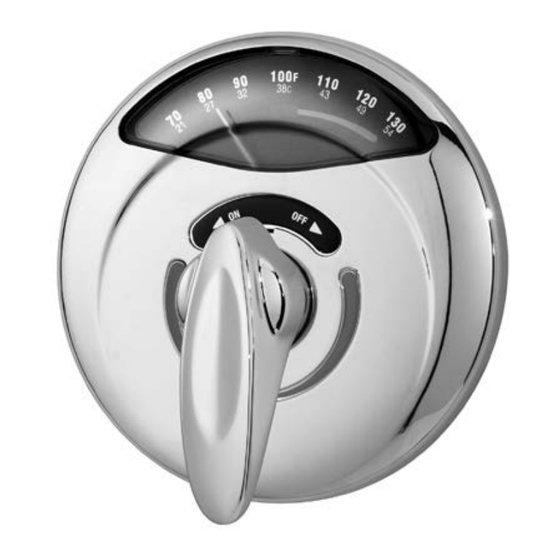
Single Handle Pressure-Balancing Mixing Valve for Shower or Tub/Shower Application
INSTALLATION, OPERATION & SERVICE INSTRUCTIONS
For California Residents
WARNING: This product contains chemicals known to the State of California to cause cancer, birth defects, or other reproductive harm.
Symmons valves, shower heads and
hand sprays comply to all known
standards, codes and specifications:
ASME A112.18.1/CSA B125.1, ASSE
1016 etc. Symmons shower heads
and hand sprays are equipped
with a 2.5 gpm (9.5 L/min) water
and energy saving flow restrictor.
This instruction sheet shows rough-in
dimensions for Models 4-500VT(X),
1-100VT(X) and 1-210VT(X). See sepa-
rate drawings enclosed with num-
bered models for applicable rough-in
dimensions.
Tools required for installation of this
product are: Phillips screw driver,
tubing cutter, teflon tape, soldering
equipment, adjustable wrench and
channel-lock pliers.
Installation of Shower System
Model 1-100VT(X) (Figure 2)
Install HOT on left and COLD on right
according to valve markings.
1. Install piping and fittings with valve
body as shown in Figure 2 or 3.
IMPORTANT: Valve rough-in is 2-1/2"
(64mm) min. — 3" (76mm) max. from
CENTERLINE OF SUPPLIES TO FACE
OF FINISH WALL. Install so that surface
indicated on plaster shield on valve
is flush with finish wall as shown in
FIGURE 1
plaster shield
1
1
4
''- 4 "
4
2
108mm
114mm
nish wall face
1
''
2
64mm min.
2
3" 76mm max.
C L
supplies
FIGURE 2
Model 1-100VT(X) Shower System
NOTE: 2-1/2" (64mm) min.
3" (76mm) max. On 2"x4"
construction, use 2-1/2"
(64mm) min. r ough-in.
Va lve inlets and outlets ar e
1/2" (13mm) IPS connections.
All floor to center dimensions optional. Concealed piping and fittings not furnished by manufacturer.
Figure 1.
2. When finishing tile wall REMOVE
(pull off; don't turn) ENTIRE PROTEC-
TIVE PLASTER SHIELD and FILL AREA
AROUND VALVE BODY WITH GROUT
OR PLASTER. DO NOT PLASTER OVER
SC-2 CAP OR SERVICE STOPS IF SO
EQUIPPED.
3. Turn on hot and cold supplies, valve
will not operate unless both hot and
cold water are turned on.
5 5/8"
143mm
9 1/2"
240mm
approx.
24"
610mm
4. This valve is equipped with a limit stop
screw to be used to limit valve handle
from being turned to excessively hot
water discharge temperatures. To
adjust, remove dome cover (SC-
13/18), place handle (VT-112) on
stem, open valve to maximum desired
temperature and turn in limit stop
screw (SC-26) until it seats. WARNING:
Failure to adjust the limit stop
screw properly may result in serious
scalding. WARNING: This shower
Advertisement

Subscribe to Our Youtube Channel
Related Manuals for Symmons SAFETYMIX VISU-TEMP 1-100VT-E-X


Summary of Contents for Symmons SAFETYMIX VISU-TEMP 1-100VT-E-X
- Page 1 INSTALLATION, OPERATION & SERVICE INSTRUCTIONS For California Residents WARNING: This product contains chemicals known to the State of California to cause cancer, birth defects, or other reproductive harm. Symmons valves, shower heads and FIGURE 2 hand sprays comply to all known...
- Page 2 Contact your factory representative or Symmons directly for information on available checks.
- Page 3 ABRASIVE CLEANERS, SOLVENTS OR AND NOT DEPEND ON FIBERGLASS ACID CLEANERS WILL DAMAGE THE WALL FOR VALVE MOUNTING SECU- FINISH AND VOID THE SYMMONS RITY. On panel walls over 1” thick, WARRANTY. install in conventional manner. (See figure 1).
- Page 4 Damage to the chrome and/or other decorative finishes on Symmons products may be a result of problem, your name, address and phone number.
Need help?
Do you have a question about the SAFETYMIX VISU-TEMP 1-100VT-E-X and is the answer not in the manual?
Questions and answers