Advertisement
Quick Links
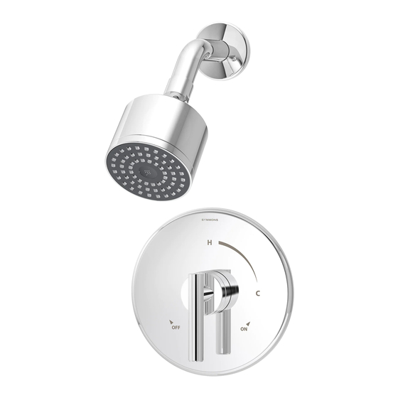
Dia Trim Series
Dia Trim Series with TA-10 Flow Control Spindle & T-12A Cap Assembly
Installation & Operation Instructions
Model Numbers
TRIM ONLY
3500-CYL-B-TRM
Shower Valve Trim
3501-CYL-B-TRM
Shower Trim
3502-CYL-B-TRM
Tub/Shower Trim
3503-H321-V-CYL-B-TRM
Hand Shower Trim
3505-H321-V-CYL-B-TRM
Shower/Hand Shower Trim
3506-H321-V-CYL-B-TRM
Tub/Shower/Hand Shower Trim
3520-B-TRM
Shower Valve Trim
3521-B-TRM
Shower Trim
3522-B-TRM
Tub/Shower Trim
3530-B-TRM
Shower Valve Trim
3531-B-TRM
Shower Trim
3532-B-TRM
Tub/Shower Trim
Compliance
•
ASME A112.18.1/CSA B125.1
Warranty
Limited Lifetime - to the original end purchaser in consumer/residential installations.
5 Years - for industrial/commercial installations.
Refer to www.symmons.com/warranty for complete warranty information.
Go to www.symmons.com/register to register your Symmons product.
Dia
®
TRIM, TA-10, T-12A
3500CYLBTRMTC
Shower Valve Trim
3501CYLBTRMTC
Shower Trim
3502CYLBTRMTC
Tub/Shower Trim
3503H321CYLBTRMTC
Hand Shower Trim
3505H321CYLBTRMTC
Shower/Hand Shower Trim
3506H321CYLBTRMTC
Tub/Shower/Hand Shower Trim
3520BTRMTC
Shower Valve Trim
3521BTRMTC
Shower Trim
3522BTRMTC
Tub/Shower Trim
3530BTRMTC
Shower Valve Trim
3531BTRMTC
Shower Trim
3532BTRMTC
Tub/Shower Trim
T-12A
TA-10
3500-CYL-B-TRM
3500CYLBTRMTC
3501-CYL-B-TRM
3501CYLBTRMTC
3502-CYL-B-TRM
3502CYLBTRMTC
3503-H321-V-CYL-B-TRM
3505-H321-V-CYL-B-TRM
3503H321CYLBTRMTC
3505H321CYLBTRMTC
3520-B-TRM
3530-B-TRM
3520BTRMTC
3530BTRMTC
3521-B-TRM
3531-B-TRM
3521BTRMTC
3531BTRMTC
3522-B-TRM
3532B-TRM
3522BTRMTC
3532BTRMTC
3506-H321-V-CYL-B-TRM
3506H321CYLBTRMTC
Advertisement

Related Manuals for Symmons Dia 3500-CYL-B-TRM


Summary of Contents for Symmons Dia 3500-CYL-B-TRM
- Page 1 3505H321CYLBTRMTC 3506H321CYLBTRMTC Compliance • ASME A112.18.1/CSA B125.1 Warranty Limited Lifetime - to the original end purchaser in consumer/residential installations. 5 Years - for industrial/commercial installations. Refer to www.symmons.com/warranty for complete warranty information. Go to www.symmons.com/register to register your Symmons product.
-
Page 2: Recommended Tools
1. Recommended Tools FIGURE 1 Adjustable Wrench Allen Wrench (2mm) Drill Phillips Screwdriver Safety Glasses Thread Seal Tape 2. Dimensions FIGURE 2 Measurements Ø 2-1/2", 64 mm 6-3/4", 171 mm 6", 152 mm Male 1/2-14 NPT thread must be recessed 1/4" (6 mm) from finished wall Ref. - Page 3 3. Parts Breakdown (Model Numbers Ending in TRMTC) Replacement Parts LIMIT STOP Item Description Part Number SCREW Cap Assy. T-12A Flow Control Spindle TA-10 IMPORTANT: Model numbers ending in TRMTC coordinate with Temptrol pressure balancing valves ordered with Test Cap. The Test Cap is used to allow pressurization of system.
-
Page 4: Parts Breakdown
7. Parts Breakdown FIGURE 7 Replacement Parts Item Description Part Number Showerhead 352SH Shower Arm 300S Flange Standard Handle T-242A Blade Handle RTS-090 Cross Handle RTS-091 Dome Cover T-19/20 Diverter Escutcheon Screws T-416A Mounting Plate Brass: Shower Escutcheon RTS-009 Screws Plastic: Mounting Plate RTS-010... - Page 5 4) Install handle to shower valve. Secure with set screw (FIGURE 8.4). FIGURE 8.3 FIGURE 8.4 9. Installation - Diverter Valve Trim 1) Secure small mounting plate to Symmons diverter valve FIGURE 9.1 FIGURE 9.2 using mounting screws (FIGURE 9.1). 2) Secure small diverter escutcheon to mounting plate.
- Page 6 11. Installation - Slide Bar Assembly 1a) Dry Wall Option: Remove upper and lower caps from slide bar brackets. Place slide bar into desired position. Using brackets as a guide, carefully drill 3/16" holes into wall. Remove slide bar and install anchors. Note: Slide bar holes and bracket holes must be aligned before drilling.
- Page 7 12. Operation (Temperature Control) 1) Turn shower handle counter-clockwise FIGURE 12.1 FIGURE 12.2 FIGURE 12.3 approximately 1/4 turn to put valve in cold position (FIGURE 12.1). 2) Turn shower handle counter- clockwise approximately 1/2 turn to put valve in warm position (FIGURE 12.2). 3) Turn shower handle counter- clockwise approximately 3/4 turn to put valve in hot position (FIGURE 12.3).
-
Page 8: 15. Troubleshooting Chart
For more information, go to www.P65Warnings.ca.gov. ■ ■ ■ ■ Symmons Industries, Inc. 31 Brooks Drive Braintree, MA 02184 Phone: (800) 796-6667 Fax: (800) 961-9621 ■ ■ ■ ■ Copyright © 2019 Symmons Industries, Inc. symmons.com gethelp@symmons.com ZV-3280 REV A 062419...
Need help?
Do you have a question about the Dia 3500-CYL-B-TRM and is the answer not in the manual?
Questions and answers