Advertisement
Quick Links
SECO-NCD5700-GEVB
NCD5700 mini Evaluation
Board User's Manual
Purpose
This document describes the use and applications for the NCD5700
gate driver mini board. The board is designed on a two layer PCB and
includes the NCD5700 driver and all the necessary drive circuitry
including isolation as can be seen in Figure 3. The board also includes
ability to solder any MOSFET or SiC MOSFET in a TO−247 high
voltage package and compatibility with SECO−GDBB−GEVB
baseboard for out−of−the−box evaluation. The board does not include
a power stage and is generic from the point of view that it is not
optimized to any particular topology. It can be used in any low−side or
high−side power switching application. For bridge configurations two
or more of these boards can be configured in a totem pole type drive
c o n f i g u r a t i o n . T h e b o a r d s c a n b e c o n s i d e r e d a s a n
isolator+driver+TO−247 discrete module.
NCD5700 Description
The NCD5700 is a high−current, high−performance stand−alone
IGBT driver for high power applications that include solar inverters,
motor control and uninterruptable power supplies. The device offers a
cost−effective solution by eliminating many external components.
Device protection features include Active Miller Clamp, accurate
UVLO, EN input, DESAT protection and Active Low FAULT
output. The driver also features an accurate 5.0 V output and separate
high and low (VOH and VOL) driver outputs for system design
convenience. The driver is designed to accommodate a wide voltage
range of bias supplies including unipolar and bipolar voltages. It is
available in a 16−pin SOIC package. The simplified block diagram is
shown in Figure 4.
Collaterals
•
SECO−NCD5700−GEVB
•
SECO−GDBB−GEVB
Figure 3. NCD5700 mini Board Schematic
© Semiconductor Components Industries, LLC, 2020
October, 2020 − Rev. 0
EVAL BOARD USER'S MANUAL
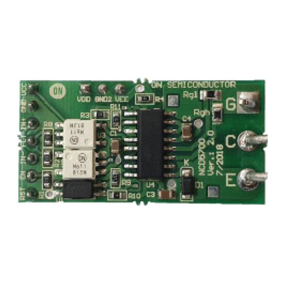
Figure 1. SECO−NCD5700−GEVB
Figure 2. Board Plugged into
Features
•
Galvanic Isolated Gate Driver Circuit
•
Demonstrates NCD5700 Driver with
Advanced Features
•
Replaceable Load Capacitor and Gate
Resistor for different Load Conditions
•
Plug−and−Play Testing with
SECO−GDBB−GEVB as seen in Figure 6
•
Minimized Form−factor for Embedding and
Testing in Application Boards or New
Designs
•
Custom Voltage Levels with External
Power Supply
1
www.onsemi.com
SECO−GDBB−EVB
Publication Order Number:
EVBUM2765/D
Advertisement

Related Manuals for ON Semiconductor SECO-NCD5700-GEVB


Summary of Contents for ON Semiconductor SECO-NCD5700-GEVB
- Page 1 SECO-NCD5700-GEVB NCD5700 mini Evaluation Board User's Manual Purpose This document describes the use and applications for the NCD5700 www.onsemi.com gate driver mini board. The board is designed on a two layer PCB and includes the NCD5700 driver and all the necessary drive circuitry EVAL BOARD USER’S MANUAL...
- Page 2 SECO−NCD5700−GEVB Figure 4. Simplified NCD5700 Block Diagram Figure 5. NCD5700 mini Board − Top and Bottom View Figure 6. NCD5700 Connected to SECO−GDBB−GEVB Auxiliary Evaluation Board www.onsemi.com...
- Page 3 SECO−NCD5700−GEVB Table 1. NCD5700 mini BOARD BOM Reference Qty per Designators Value Description Notes 0.47 mF 50 V 0.47 mF 50 V Ceramic Capacitor X7R 0805 (2012 Metric) C1, C3, C4, 0.079” L x 0.049” W (2.00 mm x 1.25 mm) 100 pF 500 V 100 pF 500 V Ceramic Capacitor C0G, NP0 0805 (2012 Metric) 0.079”...
- Page 4 SECO−NCD5700−GEVB PCB Assembly and Layers Figure 5 and Figure 7 shows the top and bottom two header connectors (P1 and P2) and power connecter we real/assembly view of the PCB. The PCB is 35 mm x 18 mm call IGBT are not assembly because of versatility of x 1 mm (length x width x height) where the width of the PCB suggested concept of mainboards.
- Page 5 SECO−NCD5700−GEVB Mounting into Existing PCB Mounting into Existing PCB − Option 2 The board can be mounted into an existing power board, If components mounted on the main PCB interfere with shown as “Main PCB” in Figure 6. If there are no mounting the EVB as described by Option 1 (Figure 8), the components or low profile surface mount components only, TO−247 leads can be formed (lead length may need to be...
- Page 6 SECO−NCD5700−GEVB TO247 TO247 Signals and /or power supply can be Signals and /or power supply can be soldered from topside soldered from topside Low voltage Secondary Low voltage Secondary signals signals power supply power supply Î Î Î Î Î Î Î Î Î Î Î Î Î Î Î Î Î Î Î Î Î Î Î Î Î Î Î Î Î Main PCB Î...
- Page 7 SECO−NCD5700−GEVB Figure 11. EVB’s PCB Mechanical Data Testing without Installing into a PCB in place and used as a load for the gate driver board. Note that The EVB can also be tested without installing into a main testing without installing into a power stage, leaves the PCB.
- Page 8 SECO−NCD5700−GEVB Figure 12. Test Configuration of EVB without Installing into Main or Base PCB Figure 13. An Example How to Use Extended Mother Board (SECO−GDBB−EVB) for Gate Drive Mini Boards Testing and Evaluating DESAT Setup output (thus turn−off the IGBT), if the saturation voltage This feature monitors the collector−emitter voltage of the rises above the V .
- Page 9 SECO−NCD5700−GEVB Blanking time is set by the value of the capacitor Cb. At the R6 = 1 kW may not be the correct resistor value for some turned−off output state of the driver, the DESAT pin is applications. If V >...
-
Page 10: Technical Support
LIMITATIONS OF LIABILITY: ON Semiconductor shall not be liable for any special, consequential, incidental, indirect or punitive damages, including, but not limited to the costs of requalification, delay, loss of profits or goodwill, arising out of or in connection with the board, even if ON Semiconductor is advised of the possibility of such damages. In no event shall ON Semiconductor’s aggregate liability from any obligation arising out of or in connection with the board, under any theory of liability, exceed the purchase price paid for the board, if any.
Need help?
Do you have a question about the SECO-NCD5700-GEVB and is the answer not in the manual?
Questions and answers