Advertisement
Quick Links
1
3 D H O B B Y S H O P . C O M
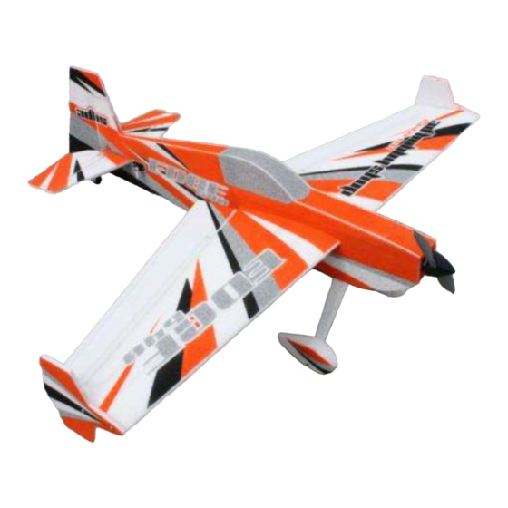
Assembly Manual- 40" EPP Edge 540
Thank you for purchasing this 3DHobbyShop ARF RC aircraft. If you have any issues, questions,
concerns or problems during assembly, please contact our tech department at:
Info@3DHobbyShop.com
or 1-830-990-6978 10am-5pm Central M-F
SAFETY in Assembly
During assembly of this aircraft, you will be asked to use sharp knives and hobby adhesives. Please
follow all safety procedures recommended by the manufacturers of the products you use, and always
follow these important guidelines:
ALWAYS protect your eyes when working with adhesives, knives, or tools, especially power tools. Safety
glasses are the best way to protect your eyes.
ALWAYS protect your body, especially your hands and fingers when using adhesives, knives, or tools,
especially power tools. Do not cut toward exposed skin with hobby knives. Do not place hobby knives on
tables or benches where they can roll off or be knocked off.
ALWAYS have a first-aid kit handy when working with adhesives, knives, or tools, especially power tools.
ALWAYS keep hobby equipment and supplies out of the reach of children.
IMPORTANT NOTE – We strive to provide the absolute best-quality ARF aircraft on the planet. However,
the ultimate success or failure of this aircraft is dependent upon proper assembly by you. If you have
questions about an assembly step, please contact us, or read the assembly thread for your airplane on
RCGroups.com before proceeding. It is always better to slow down and be sure of your assembly than to
rush through it and make a mistake which can cause a crash.
SAFETY in Flying
SAFETY NOTICE: This is NOT a toy! It is a very high-performance RC airplane capable of high speeds
and extreme maneuvers. It should only be operated by a competent pilot in a safe area with proper
supervision.
ONLY fly your aircraft in a safe, open area, away from spectators and vehicles–and where it is legal to fly.
NEVER fly over an unsafe area, such as a road or street.
NEVER fly near overhead power or utility lines. If your airplane ever becomes stuck in a line or a tree DO
NOT attempt to retrieve it yourself. Contact the authorities for assistance in retrieving your aircraft.
Power lines are DANGEROUS and falls from ladders and trees CAN KILL!
Never fly too close to yourself or spectators. Spinning propellers are DANGEROUS!
Never run your motor inside a house or building with the propeller attached – Remove the prop for safety.
Always fly within your control.
Always follow manufacturer's instructions for your radio system.
Always obtain proper insurance before flying – contact the AMA at
www.modelaircraft.org
Advertisement

Subscribe to Our Youtube Channel
Related Manuals for 3D Hobby Shop 40" EPP Edge 540


Summary of Contents for 3D Hobby Shop 40" EPP Edge 540
- Page 1 3 D H O B B Y S H O P . C O M Assembly Manual- 40” EPP Edge 540 Thank you for purchasing this 3DHobbyShop ARF RC aircraft. If you have any issues, questions, concerns or problems during assembly, please contact our tech department at: Info@3DHobbyShop.com or 1-830-990-6978 10am-5pm Central M-F SAFETY in Assembly...
-
Page 2: Required Items
REQUIRED ITEMS CA Glue – Thin and Thick ("All Purpose Welder" Glue optional, but recommended for crash repairs to EPP foam) Hobby Knife Small Phillips Screwdriver Set Metric Allen Wrenches Small Pliers Masking tape Wire Cutters Drill and drill bits Assembly Instructions –... - Page 3 Push wire landing gear leg though hole in wheel pant. Install wheel collars and wheel as shown.
- Page 4 Push wheel pant into position over wheel. Glue wheel pant to wire leg with thick CA or Welder's glue as shown.
- Page 5 Apply thick CA glue into landing gear slot on bottom of fuselage. Insert landing gear followed by plywood rectangle spacer into slot.
- Page 6 Locate rudder, tailwheel components. Locate hole in front edge of rudder.
- Page 7 Install tailwheel, collar, and wood bracket onto tailwheel wire as shown, then glue wire into rudder with thick CA or Welder glue as shown. Slide rudder hinges into slots in fin as shown. If necessary, use a hobby knife to open any slots which have become blocked with glue.
- Page 8 Use thick CA to glue the wood bracket to the bottom of the fuselage. Make sure the rudder can swing freely both directions. Apply thin CA glue to the rudder hinges. Allow to dry.
- Page 9 Insert rudder horn into slot in rudder as shown. The fit should be tight. On the other side, apply thick CA glue to the retainer and press onto the control horn post.
- Page 10 Insert the elevator into the fuselage slot (upside down and backwards, as shown) and center in the slot. Insert the horizontal stabilizer into the slot as shown, center.
- Page 11 Insert the elevator hinges into the stabilizer and use a ruler to accurately center the assembly in in the fuselage. Apply thin CA to the joint between the fuselage and horizontal stabilizer.
- Page 12 Apply thin CA glue to the elevator hinges. Inspect the clearance between the elevator and the rudder control horn. If necessary, trim the rudder horn as shown for clearance.
- Page 13 Install elevator horn in bottom of elevator using same procedure as rudder horn. Install rudder servo and pushrod as shown.
- Page 14 Run the servo leads forward to the front of the fuselage as shown. Use masking tape to hold the rudder on center.
- Page 15 Use pliers to make a bend in the wire pushrod at the servo arm. Complete the pushrod with a second bend as shown and trim as shown.
- Page 16 Install Z-bend into servo arm as shown. Install elevator servo. Make and install elevator pushrod using the same steps.
- Page 17 The brushless motor installs from the front as shown. Motors are different lengths depending on type, use spacers as shown for shorter brushless motors.
- Page 18 Attach motor to firewall with wood screws as shown. Slide main wing into fuselage as shown.
- Page 19 Center the wing using the aileron servo wire openings. Glue wing to fuselage with thick CA.
- Page 20 Slide aileron hinges into wing as shown. Use a hobby knife to open any hinge slots as necessary. Make sure the aileron is inset slightly from the wingtip to allow room for the SFG.
- Page 21 Apply thin CA glue to the aileron hinges. Install the aileron horns and aileron servo mounts with thick CA glue.
- Page 22 Thread aileron servo wires through the wing and into the top of the fuselage. Make aileron pushrods like the elevator and rudder pushrods.
- Page 23 Install pushrod onto servo arm as shown. Glue landing gear leg covers onto wire legs with thick CA or Welder glue.
- Page 24 Install SFG onto wingtip with wood screws as shown. Run motor wires through firewall opening as shown.
- Page 25 Install ESC into bay on bottom of fuselage as shown. Run ESC connections up into battery area.
- Page 26 Balancing – Balance your Edge 2.5 inches (62mm) behind the leading edge of the wing where the wing meets the fuselage for your maiden flight. This is approximately on the forward edge of the carbon wing spar tube. Move the flight battery and/or add weight to the nose or tail to balance as necessary. Remember –...
- Page 27 We hope you enjoy your 3D HOBBY SHOP Aircraft. Be sure to look for new aircraft and products coming soon from 3 D H O B B Y S H O P . C OM Copyright 2009 3D Hobby Shop...
Need help?
Do you have a question about the 40" EPP Edge 540 and is the answer not in the manual?
Questions and answers