Table of Contents
Advertisement
Quick Links
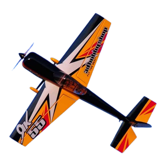
Assembly Manual / Airframe – 60" Yak 55M
Thank you for purchasing this 3DHobbyShop ARF RC aircraft. If you have any issues,
questions, concerns or problems during assembly, please contact our tech department at:
Info@3DHobbyShop.com or 717-814-5316 10am-4pm Eastern Monday thru Thursday.
SAFETY in Assembly
During assembly of this aircraft, you will be asked to use sharp knives and hobby adhesives.
Please follow all safety procedures recommended by the manufacturers of the products you use,
and always follow these important guidelines:
•
ALWAYS protect your eyes when working with adhesives, knives, or tools, especially
power tools. Safety glasses are the best way to protect your eyes.
•
ALWAYS protect your body, especially your hands and fingers when using adhesives,
knives, or tools, especially power tools. Do not cut toward exposed skin with hobby
knives. Do not place hobby knives on tables or benches where they can roll off or be
knocked off.
•
ALWAYS have a first-aid kit handy when working with adhesives, knives, or tools,
especially power tools.
•
ALWAYS keep hobby equipment and supplies out of the reach of children.
SAFETY in Flying
This is NOT a toy! It is a very high-performance RC airplane capable of high speeds and
extreme maneuvers. It should only be operated by a competent pilot in a safe area with proper
supervision.
•
ONLY fly your aircraft in a safe, open area, away from spectators and vehicles and
where it is legal to fly. NEVER fly over an unsafe area, such as a road or street.
•
NEVER fly near overhead power or utility lines. If your airplane ever becomes stuck in
a line or a tree DO NOT attempt to retrieve it yourself. Contact the authorities for
assistance in retrieving your aircraft. Power lines are DANGEROUS and falls from
ladders and trees CAN KILL!
•
Never fly too close to yourself or spectators.
•
Spinning propellers are DANGEROUS!
Never run your motor inside a house or building with the propeller attached Remove the
prop for safety. Always fly within your control.
•
Always follow manufacturers instructions for your radio system.
•
Always preform a pre-flight check of your aircraft to be certain of the aircraft's
airworthiness.
1
Advertisement
Table of Contents

Subscribe to Our Youtube Channel
Related Manuals for 3D Hobby Shop 60 inch Yak 55M


Summary of Contents for 3D Hobby Shop 60 inch Yak 55M
- Page 1 Assembly Manual / Airframe – 60” Yak 55M Thank you for purchasing this 3DHobbyShop ARF RC aircraft. If you have any issues, questions, concerns or problems during assembly, please contact our tech department at: Info@3DHobbyShop.com or 717-814-5316 10am-4pm Eastern Monday thru Thursday. SAFETY in Assembly During assembly of this aircraft, you will be asked to use sharp knives and hobby adhesives.
-
Page 2: Limits Of Responsibility
3D Hobby Shop provides high-quality aircraft and components to it's customers and end users. These aircraft and components are assembled by the end user to produce a flying model. It is beyond 3D Hobby Shop's control to monitor the end user's completed aircraft. Therefore, 3D Hobby Shop in no way accepts or assumes responsibility or liability for damages resulting from the end user assembled product. -
Page 3: Let's Get Started
WRINKLES : Your airplane was packed in plastic at the factory without any wrinkles in the covering. You may notice some wrinkles now; more likely, you will notice a few in a day or two or the first time you take the plane out to the flying field. -
Page 4: Landing Gear
Landing Gear Install the wheels onto the axles and secure with the wheel collars, as shown. Use blue Loctite on wheel collar set screws. Slide one wheel/axle assembly into a wheel pant, and install the wheel assembly on the landing gear leg. - Page 5 Attach the gear to the fuselage with short 3mm screws, use loctite.
- Page 6 Install gear cover plate as shown, with clear tape, thick CA or epoxy glue.
- Page 7 Fuselage Remove covering over horizontal stabilizer slot on both sides of fuselage as shown. Remove covering over elevator servo opening on LEFT side of the fuselage as shown. Remove covering over wing spar tube hole and wing pin holes in fuselage as shown.
- Page 8 Remove a square of covering on bottom of fuselage behind wing as shown. This is to allow cooling air to exit fuselage. Now is a good time to go over all joints of the motor box with this CA.
-
Page 9: Horizontal Stabilizer
Horizontal Stabilizer Install the horizontal stabilizer in the fuselage, but do not glue at this time. Next, install the wing tube in the fuselage and sight from the back and notice if the horizontal stabilizer and wing tube are parallel to each other. - Page 10 Measure the distance of leading edge of stabilizer to wing tube. Adjust until even. Be certain all four measurements are even before glueing. When stabilizer is centered and aligned, drip Thin CA glue onto the stab-to-fuselage joint top and bottom. NOTE: We do not remove any covering form the horizontal stabilizer. This keeps the stabilizer strong, and thin CA makes an excellent joint to covering material.
- Page 11 Install the elevator half with the fiberglass joiner rod onto the stabilizer. Makes sure it flexes easily at least 45 degrees up and 45 degrees down, and has approx 1/32” of gap in the hingeline. Apply thin CA glue to the hinges, 2 large drops on each. Place a piece of removable tape on the elevator counterbalance as shown.
- Page 12 Immediately place a piece of tape on the left elevator counterbalance to the stabilizer. Apply thin CA to the elevator hinges and allow everything to dry. Once the elevator assembly is dry, install the elevator control horn. Be sure to sand the portion...
- Page 13 installed in the elevator. Note picture for elevator control horn slot location. Open the slot and install control horn with medium CA. Install elevator servo and pushrod as shown. The ball links are mounted to the elevator control arm and servo arm with 2mm bolts, washers and lock nuts.
-
Page 14: Rudder Installation
Rudder Installation Open the slot for the rudder control horn. Use picture for reference in locating the slot. Rough the control horn with sand paper where the glue joint will be, so the CA may adhere better. Install the rudder control horn with medium CA. Center the rudder control horn in the rudder. -
Page 15: Tailwheel Assembly
Install the rudder, take your time to align it, and make sure it swings freely. Apply thin CA to the rudder hinges. Tailwheel Assembly Before installation, use blue Loctite on all set screws. - Page 16 The tiller wire will need to be bent slightly to be inserted in the installed bracket on the bottom of the rudder. Attach the tailwheel assembly to the fuselage with two wood screws as shown.
- Page 17 Rudder pull-pull linkage Install rudder servo in fuselage as shown. We are using a 2” double servo arm. Install the servo arm as close to perpendicular as possible. Then use your radio's subtrim as needed. The rudder pull-pull cables are assembled as shown in the above diagram. Assemble end of pull-pull wire as shown, double-looping the wire through the brass crimp sleeve before crimping.
- Page 18 It is easiest to connect the pull-pull cables to the rudder servo first, then connect to the rudder control arms. Tape the rudder counterbalance with removable tape. Be sure the rudder servo is centered. Install the ball links on the rudder control horns. Assemble the front ends of the pull-pull cables as shown, double looping the wire through the crimp sleeve.
-
Page 19: Power System Installation
Power System Installation The firewall of the Yak is arranged to allow the widest possible selection of motors to fit. Extra space has been provided for long motors and long prop adaptors. For this reason, if your motor is compact, you will need to supply spacers to extend the motor forward as shown. -
Page 20: Cowl Installation
Cowl Installation The cowl is mounted onto the fuselage with 4 wood screws. These screws go into the small plywood squares on the front inside of the fuselage. The following procedure is helpful to be sure the wood screws hit the plywood squares. First, make small holes into the plywood squares through the covering, with the cowl and canopy off. - Page 21 Use masking tape to hold the cowl in place. Drill pilot holes for the wood screws using the paper markers as a guide.
- Page 22 Install the 4 wood screws. Tip: remove screws and cowl, soak holes left in mounting tabs with thin CA. This will strengthen the area. Mount cowl again after CA is completely dry.
- Page 23 Wings Install the ailerons. Adjust the gap (approximately 1/32”) for maxim throw. Glue the aileron hinges with two large drops of CA per hinge. Open the aileron servo opening and control horn slot. Here we have cut an X in the covering for the aileron servo, no need to remove the covering over the opening.
- Page 24 Rough the control horn as with the elevator control horn. Glue with medium CA. Install the aileron servo, using the installed strings to guide the servo wire to the wing root.
- Page 25 Install aileron servo as shown. Assemble the aileron pushrod using two ball links. We are using a 1” servo arm for the ailerons. NOTE: the correct size aileron pushrods are included in the bag marked “REPLACEMENT HARDWARE.” Repeat the aileron assembly for other wing. Mount the wings to the fuselage using the aluminum thumbscrews.
-
Page 26: Receiver Mounting
Receiver Mounting Locate the balsa receiver mount marked “Rx”. You can mount your receiver to this mount with Velcro and use CA glue to mount the balsa to the airframe. Side-Force-Generators (SFG) SFG's are included with two spacers. The small spacer can be used with the SFG's for conventional placement. - Page 27 The SFG's are mounted with 2 wood screws. Locate the precut hole in both spacers and SFG. Note: additional longer wood screws are supplied in hardware bag marked “REPLACEMENT HARDWARE.”...
- Page 28 After your first flights, check all control connections and motor and prop mounts for tightness. Thank you for your purchasing the 3D Hobby Shop 60” Yak 55. We hope you enjoy it! Be sure to look for new aircraft and products coming soon from 3D HOBBYSHOP.COM...
Need help?
Do you have a question about the 60 inch Yak 55M and is the answer not in the manual?
Questions and answers