Table of Contents
Advertisement
Quick Links
1
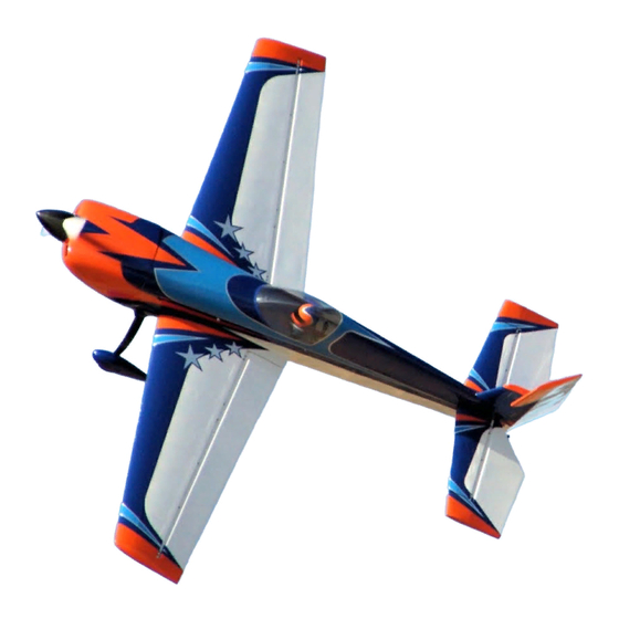
Assembly Manual / Airframe – 103" Extra 330SC
Designed by Scott Stoops
Thank you for purchasing this 3DHobbyShop ARF RC aircraft. If you have any issues, questions, concerns or
problems during assembly, please contact our tech department at:
Info@3DHobbyShop.com
or 1-830-990-6978 10am-5pm Central M-F
SAFETY in Assembly
During assembly of this aircraft, you will be asked to use sharp knives and hobby adhesives. Please follow all safety
procedures recommended by the manufacturers of the products you use, and always follow these important guidelines:
ALWAYS protect your eyes when working with adhesives, knives, or tools, especially power tools. Safety glasses are the
best way to protect your eyes.
ALWAYS protect your body, especially your hands and fingers when using adhesives, knives, or tools, especially power
tools. Do not cut toward exposed skin with hobby knives. Do not place hobby knives on tables or benches where they can
roll off or be knocked off.
ALWAYS have a first-aid kit handy when working with adhesives, knives, or tools, especially power tools.
ALWAYS keep hobby equipment and supplies out of the reach of children.
IMPORTANT NOTE – We strive to provide the absolute best-quality ARF aircraft on the planet. However, the ultimate
success or failure of this aircraft is dependent upon proper assembly by you. If you have questions about an assembly
step, please contact us, or read the assembly thread for your airplane on RCGroups.com before proceeding. It is always
better to slow down and be sure of your assembly than to rush through it and make a mistake which can cause a crash.
SAFETY in Flying
SAFETY NOTICE: This is NOT a toy! It is a very high-performance RC airplane capable of high speeds and extreme
maneuvers. It should only be operated by a competent pilot in a safe area with proper supervision.
ONLY fly your aircraft in a safe, open area, away from spectators and vehicles–and where it is legal to fly.
NEVER fly near overhead power or utility lines. If your airplane ever becomes stuck in a line or a tree DO NOT attempt to
retrieve it yourself. Contact the authorities for assistance in retrieving your aircraft. Power lines are DANGEROUS and
falls from ladders and trees CAN KILL!
Never fly too close to yourself or spectators. Spinning propellers are DANGEROUS!
Never run your motor inside a house or building with the propeller attached – Remove the prop for safety.
Always fly within your control.
Always follow manufacturer's instructions for your radio system.
Always obtain proper insurance before flying – contact the AMA at
www.modelaircraft.org
Advertisement
Table of Contents

Related Manuals for 3D Hobby Shop 103" Extra 330SC


Summary of Contents for 3D Hobby Shop 103" Extra 330SC
- Page 1 Assembly Manual / Airframe – 103” Extra 330SC Designed by Scott Stoops Thank you for purchasing this 3DHobbyShop ARF RC aircraft. If you have any issues, questions, concerns or problems during assembly, please contact our tech department at: Info@3DHobbyShop.com or 1-830-990-6978 10am-5pm Central M-F SAFETY in Assembly During assembly of this aircraft, you will be asked to use sharp knives and hobby adhesives.
- Page 2 REQUIRED ITEMS CA Glue – Thin and Medium or Thick Hobby Knife Small Phillips Screwdriver Set Metric Allen Wrenches Scissors Small Pliers Wire Cutters Adjustable wrench Masking tape Drill and drill bits Threadlocker (Blue Loctite) Polyurethane and/or 30min epoxy glue Vaseline/petroleum jelly Rubbing alcohol Optional –...
- Page 3 Covering Removal (Fuselage) Canopy Bolt Wing Tube (Factory Cut) Wing Safety Wing Bolt Anti-Rotation Pin Anti-Rotation Pin Aileron Servo Extensions Using a soldering iron or hobby knife, remove covering from forward fuselage areas. (Pictured above) Next remove covering for the horizontal stabilizer bolts. Carbon tube and servo wire holes are factory cut.
-
Page 4: Tail Wheel
Use short 4-40 bolts and washers to secure cover. Also remove covering over the rear access port as shown. This port can be used to access the guide-string for the elevator servo extensions, and can also be used for maintenance and repairs to the tail-wheel mount. -
Page 5: Rudder Hinging
3/32 Allen Wrench/Driver 2.7” Install tail wheel assembly using 3x-4-40 bolts and washers. Use blue loctite on the bolts. Rudder Hinging The 103” Extra uses a removable rudder. Slide the included rudder wire down through the hole in the top of the rudder, through all of the hinges and secure at the bottom with the included collar. -
Page 6: Main Landing Gear
Main Landing Gear Locate all landing gear parts and hardware. Each axle assembly incorporates two wheel collars. The first is used to prevent the wheel from rubbing on the inner side of the wheel pant, and the second outer collar to secure wheel. - Page 7 Use a standard size (#408) Dremel sanding drum. Remove enough material to make room for the axle. Slide cuffs into position on the landing gear. Perform a quick fit check on the fuselage to verify cuffs are properly oriented.
- Page 8 Use a wrench (1/2” pictured) or needle nose pliers to hold axle while securing nylock nut. Insert the wheels and axles into main landing gear with the nylock nuts. (13mm nylock nuts) Make sure wheel pants are installed facing forward! Install wheel pants facing forward along with the thicker portion of the...
- Page 9 Using a 3/32 allen wrench check and tighten all landing gear aluminum angle bracket bolts. 9/64 allen wrench/driver. Install the main gear to the fuselage using 4 x 4-40 bolts, washers, and locknuts. Then secure landing gear cover plate using epoxy.
- Page 10 Install landing gear cuffs using the supplied short 4mm flanged screws. Again using blue loctite. Elevator and Aileron Control Horns Your Extra 330SC features phenolic control horns. The slots for the horns are pre-cut on all control surfaces. Aileron and Elevator Rudder Control Control Horns.
- Page 11 Assembling the control horns now will help to accurately align the horns when gluing in place. Note: Control horns can be installed using Polyurethane glue OR 30-minute epoxy. The instructions will detail the use of PU-Glue. Locate the control horn location for each control surface and remove the covering from the double slots on each surface.
- Page 12 Insert control horn into slots, (do not glue) and trace around the perimeter of the horn with a Sharpie. Using a soldering iron or sharp xacto knife, remove covering inside of your marking. The Sharpie line can be easily removed using rubbing or denatured alcohol.
- Page 13 Slightly dampen the gluing surface with water. Apply glue in both slots and on the balsa mounting surface. Insert horn. Be prepared to wipe away foaming PU glue for the first 10-60 minutes using rubbing/denatured alcohol.
-
Page 14: Rudder Control Horn Installation
Recommended dual aileron servo installation pictured. Repeat the process and install the aileron control horns. This is also a good time to remove the covering from the aileron servo openings. Rudder Control Horn Installation Your Extra 330SC is equipped with two rudder servo locations. If you use a lightweight engine such as most 85CC singles and light 100CC, use the forward rudder servo locations in the fuselage and the pull-pull cables. - Page 15 Apply glue to the center of the two horn pieces as well as both sides of the rudder. You do not need to squeeze glue into the control horn slots in the rudder. Slide control horns into position and install second ball link to ensure proper alignment as glue cures. Carefully check and center control horns while removing the foaming PU glue.
-
Page 16: Horizontal Stabilizer Installation
Horizontal Stabilizer Installation Install the horizontal stabilizers onto the fuselage using two carbon-fiber spar tubes. The horizontal stabs are retained by two 4-40 screws on each side as shown. Please use thread-locker on these screws, and inspect frequently, as vibrations may loosen them over time. Wing Attachment The wing attaches to the fuselage with one nylon thumb-screw and one safety clip per side. - Page 17 Canopy The canopy hatch is supplied with the floor pre-installed. The rear of the hatch is left open so you can easily install a pilot head and cockpit control panel. When you have completed any work inside the cockpit, use a small amount of CA glue to install the balsa rear plate onto the canopy hatch.
- Page 18 Note: Please use blue Loctite on all cowl fasteners. Start by installing 4x 4-40 bolts as pictured above to secure the lower cowling half. Slide the top cowling half into position and install the single 4-40 bolt as pictured above.
- Page 19 Then install all 4-40 bolts on the sides and forward portions of the cowling. 7.25” For optimal spinner to cowling fit, adjust your engine crankshaft flange distance to 7.25” as seen above.
- Page 20 If you have mounted your engine properly, you should have a 1/8 to 3/16 inch gap between the cowling and the back of the spinner plate. Adjust your motor as necessary to achieve this. Electric Power Installation (For gas engine installation, refer to 100CC installation manual) The 103”...
-
Page 21: Control Setup
Center of Gravity Measure at WINGTIP. 4.5 inches back from leading edge is preferred. Allowable range is 4.0” to 5.0” 3D Hobby Shop wishes you the very best with your new 103” Extra 330SC! FLY LOW! FLY LOW! FLY LOW!
Need help?
Do you have a question about the 103" Extra 330SC and is the answer not in the manual?
Questions and answers