Advertisement
Quick Links
1
3 D H O B B Y S H O P . C O M
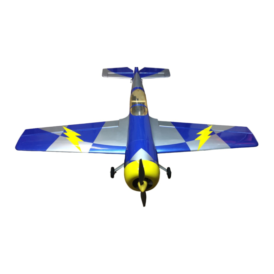
Assembly Manual- 57" Sukhoi 26MX
Thank you for purchasing this 3DHobbyShop ARF RC aircraft. If you have any issues, questions,
concerns or problems during assembly, please contact our tech department at:
Info@3DHobbyShop.com
or 1-830-990-6978 10am-5pm Central M-F
SAFETY in Assembly
During assembly of this aircraft, you will be asked to use sharp knives and hobby adhesives. Please
follow all safety procedures recommended by the manufacturers of the products you use, and always
follow these important guidelines:
ALWAYS protect your eyes when working with adhesives, knives, or tools, especially power tools. Safety
glasses are the best way to protect your eyes.
ALWAYS protect your body, especially your hands and fingers when using adhesives, knives, or tools,
especially power tools. Do not cut toward exposed skin with hobby knives. Do not place hobby knives on
tables or benches where they can roll off or be knocked off.
ALWAYS have a first-aid kit handy when working with adhesives, knives, or tools, especially power tools.
ALWAYS keep hobby equipment and supplies out of the reach of children.
IMPORTANT NOTE – We strive to provide the absolute best-quality ARF aircraft on the planet. However,
the ultimate success or failure of this aircraft is dependent upon proper assembly by you. If you have
questions about an assembly step, please contact us, or read the assembly thread for your airplane on
RCGroups.com before proceeding. It is always better to slow down and be sure of your assembly than to
rush through it and make a mistake which can cause a crash.
SAFETY in Flying
SAFETY NOTICE: This is NOT a toy! It is a very high-performance RC airplane capable of high speeds
and extreme maneuvers. It should only be operated by a competent pilot in a safe area with proper
supervision.
ONLY fly your aircraft in a safe, open area, away from spectators and vehicles–and where it is legal to fly.
NEVER fly over an unsafe area, such as a road or street.
NEVER fly near overhead power or utility lines. If your airplane ever becomes stuck in a line or a tree DO
NOT attempt to retrieve it yourself. Contact the authorities for assistance in retrieving your aircraft.
Power lines are DANGEROUS and falls from ladders and trees CAN KILL!
Never fly too close to yourself or spectators. Spinning propellers are DANGEROUS!
Never run your motor inside a house or building with the propeller attached – Remove the prop for safety.
Always fly within your control.
Always follow manufacturer's instructions for your radio system.
Always obtain proper insurance before flying – contact the AMA at
www.modelaircraft.org
Advertisement

Related Manuals for 3D Hobby Shop Sukhoi 26MX


Summary of Contents for 3D Hobby Shop Sukhoi 26MX
- Page 1 3 D H O B B Y S H O P . C O M Assembly Manual- 57” Sukhoi 26MX Thank you for purchasing this 3DHobbyShop ARF RC aircraft. If you have any issues, questions, concerns or problems during assembly, please contact our tech department at: Info@3DHobbyShop.com...
- Page 2 That dream got a little closer to reality when I started doing model development for 3D Hobby Shop in 2006. At some point in late 2007, both Ben and I made a commitment to model the Sukhoi. Setting our sights rather high, we aimed to design what would be the premier Sukhoi model on the market, incorporating not only outstanding flying characteristics, but also many of the scale features rarely seen on Sukhoi models.
-
Page 3: Required Items
REQUIRED ITEMS CA Glue – Thin and Medium or Thick Hobby Knife Small Phillips Screwdriver Set Metric Allen Wrenches Scissors Small Pliers Masking tape Wire Cutters Drill and drill bits Optional – Heat gun and covering iron Threadlocker (Blue Loctite) For Glow Fuel Engine –... - Page 4 Install the wheels onto the axles and secure with the wheel collars, as shown. Slide one wheel/axle assembly into a wheel pant, and install the wheel assembly on the landing gear leg. Tighten the locknut as shown to secure the assembly onto the gear leg. Only do ONE assembly at this time.
- Page 5 Install one wood screw through the gear leg into the wheel pant as shown, going in half-way. Remove the screw, cut ½ of the screw off with wire cutters, and re-install as shown. Slide the gear leg through the slot as shown, and secure the gear to the fuselage with short 3mm screws. Repeat wheel and pant assembly for other side.
- Page 6 Locate rudder, remove covering over rudder control horn slot with hobby knife or hot soldering iron. Insert double-sided rudder horn into slot as shown. Make sure rudder horn is centered and apply several drops of thin CA to secure the rudder horn. Measure back 2.5”...
- Page 7 Drill a 1/16 inch hole on your mark, and install the tiller holder with thick CA glue. Install rudder onto fuselage and apply 2 large drops of thin CA to each hinge. Install tail wheel as shown. Use two wood screws to secure bracket to fuselage. Remove the set screws in the tailwheel assembly, apply loctite and re-tighten.
- Page 8 Remove covering over cooling outlets on bottom of fuselage, as shown. Remove covering as shown from horizontal stabilizer opening and rudder pull-pull wire slot. Remove covering from the elevator servo opening on the left side of the fuselage as shown. Install the wings (without ailerons) NOTE: the wing tube is packed in its travel holder inside one of the wing bags.
- Page 9 Once the stab is aligned, apply thin CA glue to the joint, top and bottom. Note that we do not cut into the covering of the horizontal stabilizer for this type of installation. CA glue bonds very well to covering material. If your stab joint is not tight enough for thin CA glue, or if you have to trim the opening to align the stab, you can use thick CA glue as well.
- Page 10 Install both elevator halves as shown. Make sure you can flex the elevators easily 45 degrees up and down before gluing each hinge with a few large drops of thin CA glue. Install the elevator servos on each side as shown. Assemble the elevator pushrods as shown.
- Page 11 When you have installed the elevator pushrod as shown on each elevator half, be SURE to use medium or thick CA glue to lock the 2mm nuts in place. IF you do not lock the 2mm nuts holding the pushrods, the nuts will vibrate loose and your plane WILL crash. END of dual elevator servo install section.
- Page 12 Locate the phenolic elevator joiner and the left elevator. Use a generous amount of CA glue to install both the joiner and the elevator control horn into the left elevator as shown. Insert the elevator into the stabilizer, make sure it flexes easily 45 degrees up and down, and glue the hinges with large drops of thin CA glue.
- Page 13 Apply a generous amount of medium or thick CA glue to the slot in the right elevator and install the right elevator onto the stab with thin CA on the hinges. Hold perfectly straight as the glue dries, or use masking tape to hold the elevator straight until the glue dries. If you are using a single HS-225MG (or 5245MG) then you can install it into the elevator servo slot.
- Page 14 Assemble the elevator pushrod as shown, using the carbon tube stiffener. Once the elevator pushrod is assembled and the length checked for accuracy, use thin CA on the joints of the carbon tube and ball links to lock the assembly together. Use 2mm bolts, washers and nuts to assemble the pushrod onto the servo arm and elevator horn as shown.
- Page 15 Route elevator servo wire (or wires) as shown to keep them away from the rudder pull-pull wires. Mount the rudder servo as shown.
- Page 16 Assemble the ball links and pull-wire ends onto the rudder horn as shown with 2mm bolts, washers and nuts. Be SURE to lock the nuts with medium or thick CA glue. Install the rudder servo arm onto the servo. Screw the pull-cable ends into the ball joints several turns, but not all the way –...
- Page 17 Assemble the pull-pull wires onto the rudder horn as shown, double-looping the wire through the bras crimp, sleeve. Crimp the brass crimp sleeve tightly with pliers and apply a drop of thin CA to the crimp. Be SURE to use medium or thick CA to lock the 2mm nuts on the rudder control horn.
- Page 18 When you are satisfied with the fit of both pull-pull cables, crimp the sleeves tightly, apply a drop of thin CA to each sleeve, and cut off the excess cable. Electric Motor Install Using included 4mm allen head bolts, attach the electric motor mount to the firewall as shown.
- Page 19 Drill the motor mounting pattern as needed and mount your brushless motor as shown, using threadlocker. Mount the ESC as shown and restrain the wires with zip ties. Glow engine install Install notes: The structure of the 57” Sukhoi is designed very light, and requires reinforcement to withstand the vibration of a glow engine.
- Page 20 Use CA glue to install the plywood pieces that overlay the front of the fuselage as shown. DO NOT install the motor box top piece at this time, because we will need access to the inside of the box for several more steps. Place the varnished side of the wood to the outside.
- Page 21 Also brush the epoxy onto the interior of the motor box, the fuel-tank tray, the interior wood in the canopy area, and also on the bare wood of the wing saddle areas. This fully adheres the plywood overlay pieces to the motor box and seals the wood against oil and glow fuel.
- Page 22 Mount your engine with appropriate mounting hardware. NOTE: You can mount your engine upside-down (as shown) or right-side-up. Mounting upside-down allows you to direct the muffler out the bottom of the cowl, resulting a nicer appearance than having a muffler coming out the top of the cowl. Your kit includes two throttle servo boxes, one for the Hitec Hs-65 micro servo, and one for a full-size servo.
- Page 23 Shown above is the recommended mounting of the Hs-65 throttle servo for a 4-stroke engine. There are many other ways to mount the throttle servo for different engines with carburetors in other locations. There is also a cutout for the Hs-65 servo throttle servo in the fuselage interior for use with an upright-mounted engine.
- Page 24 Slide the metal end caps onto the tubes and insert the screw (do not tighten it yet). Bend the long vent tube up as shown. Assemble the clunk as shown, cut the clunk line so that the clunk cannot touch the back of the tank, but is close (1/4 inch away from the back of the tank) as shown.
- Page 25 Place a piece of foam rubber between the tank and tray. Mount the tank to the tray with Zip ties as shown. Plumb the tank to the engine, with the clunk line to the carburetor, the vent line to muffler pressure, and the third line as the fill line. It should be plugged during flight.
- Page 26 We recommend the use of an exhaust extension/diverter as shown, to direct exhaust away form the airplane. Also note the vent line exiting the cowl, this is the crankcase vent for the 4-stroke engine, which can expel oil and needs to be vented outside as shown. The cowl is mounted onto the fuselage with 4 wood screws.
- Page 27 Remove the cowl and screws and soak the plywood mounting tabs in thin CA glue. This will strengthen the mounting tabs. Re-install the screws. NOTE: On the glow version, these cowl screws are under high stress. Check them frequently for tightness. Cowls on glow-powered planes tend to be removed more often than cowls on electrics.
- Page 28 Install the servo with the output shaft to the back of the wing. Assemble the aileron pushrods like you did the elevator pushrods. Install the aileron pushrods with 2mm bolts, washers, and nuts. Be SURE to use medium or thick CA glue to lock the 2mm nuts in place. Using a hobby knife or soldering iron, remove the covering over the side window openings as shown.
- Page 29 After your first flights, check all control connections and motor and prop mounts for tightness. We hope you enjoy your 3D HOBBY SHOP Aircraft. Be sure to look for new aircraft and products coming soon from...
- Page 30 3 D H O B B Y S H O P . C OM Copyright 2008 3D Hobby Shop...
Need help?
Do you have a question about the Sukhoi 26MX and is the answer not in the manual?
Questions and answers