Advertisement
Quick Links
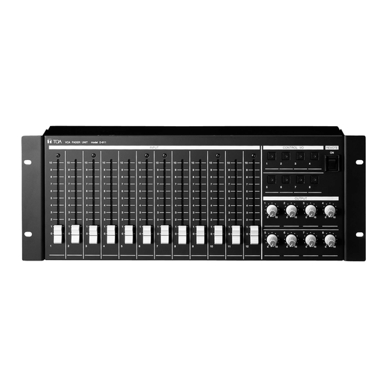
D-911 VCA FADER UNIT
Thank you for purchasing TOA's D-911 VCA Fader unit.
Please carefully follow the instructions in this manual to ensure long, trouble-free use of your equipment.
1. GENERAL DESCRIPTION
The D-911 VCA Fader Unit is designed to remotely control
the digital mixer with the D-984VC VCA Control Module
installed. Connecting to the D-984VC permits volume
adjustment of input and output channels and contact
controls of the digital mixer.
2. HANDLING PRECAUTIONS
• Connect the D-911 to the
D-984VC VCA Control
Module installed in the
digital mixer. Connect each
of eight terminals to the D-
984VC's terminal of the
same name by way of the
fully-connected straight cable as shown on the right.
• Use the D-901 firmware of version 3.0 or later. Firmware
versions earlier than it cannot be used in conjunction with
the fader unit.
The firmware version
number can be confirmed
on the D-901's front
panel-mounted display.
If your firmware version is
old, download the latest software program and the "D901
PC software instruction manual" from the TOA Internet
product data site [http://www.toa-products.com/]. For the
update procedure, refer to the instruction manual.
• For channels with stereo link or group settings
established at the digital mixer, only the lowest numbered
channel in the preset link or group is enabled.
• Fader position "10" of the D-911 provides the channel
gain set by the digital mixer. As a guide, knob position 8
provides about 10 dB below the gain set by the D-901.
4. SPECIFICATIONS
Power Supply
5 V DC (supplied from the optional D-984VC)
Connector
RJ45 connector x 8
Input Fader Control
Input fader (100 mm) x 12
Output Volume Control
Output volume control x 8
Contact Control
Illuminated switch x 8
Remote Output
No-voltage make contact output
(contact capacity: 30 V DC, 4 A)
Remote Switch
Seesaw switch for activating the remote function
of the power distributor
Finish
Panel: Pre-coated steel plate, black (30% glossy)
Dimensions
482.6 (w) x 177 (h) x 61.3 (d) mm
(excluding projection)
Weight
2.7 kg
[Connection]
1
1
2
2
3
3
4
4
5
5
6
6
1 – 8
1 – 8
7
7
8
8
[Display example]
T O A
D - 9 0 1
S e r i e s
S o f t w a r e
V e r 3 . 0 0
INSTRUCTION MANUAL
3. BLOCK DIAGRAM
DC
VCA
IN CH 1-6
DC
VCA
IN CH 7-12
DC
VCA
OUT CH 1-4
DC
VCA
OUT CH 5-8
Make contact
CTRL
IN 1-4
DC
CTRL
OUT 1-4
CTRL
IN 5-8
CTRL
OUT 5-8
• Accessories
Fader knob (Red, Yellow)* .............................. 3 each
Volume knob (Red)* ................................................ 2
Rack mounting screw 5 x 12 (with plane washer) ... 4
Rack mounting bracket (preinstalled on the unit) .... 2
* Convenient for color coding to distinguish
channels to which stereo link or group settings
are assigned.
Note
The design and specifications are subject to
change without notice for improvement.
D-911
1
6
7
12
1
4
5
8
1
4
1
4
5 – 8
Same as above
Advertisement

Subscribe to Our Youtube Channel
Related Manuals for Toa D-911


Summary of Contents for Toa D-911
- Page 1 Please carefully follow the instructions in this manual to ensure long, trouble-free use of your equipment. 1. GENERAL DESCRIPTION 3. BLOCK DIAGRAM The D-911 VCA Fader Unit is designed to remotely control the digital mixer with the D-984VC VCA Control Module installed. Connecting to the D-984VC permits volume...
- Page 2 Setting the Remote (activation) switch (3) to the ON These terminals are used exclusively for the D-984VC position closes the output. VCA Control module. Use an RJ45 connector for connection. Note Avoid connecting any other than the D-984VC to these terminals. URL: http://www.toa.jp/ 133-12-943-4A...
Need help?
Do you have a question about the D-911 and is the answer not in the manual?
Questions and answers