Table of Contents
Advertisement
Quick Links
FLEXTECH™
HUMIDIFIED
HOLDING CABINET
MODeL
FTU-5
This document is prepared for trained Duke service technicians. It is not to be used by anyone not properly
qualified to perform these procedures.
This Service Manual is not all encompassing. If you have not been trained on servicing this product, be sure to
read the manual completely before attempting servicing. Be sure all necessary tools, test equipment, and skills are
available. Those procedures for which you do not have the proper skills and test equipment must be performed
only by a qualified Duke trained service technician.
This manual is Copyright © 2014 Duke Manufacturing Co. All rights reserved.
Reproduction without written permission is prohibited. Duke is a registered
SM-PH-FT-0011
Please read this manual completely before attempting
to install, operate or service this equipment.
trademark of the Duke Manufacturing Co.
Duke Manufacturing Co.
2305 N. Broadway
St. Louis, MO 63102
Phone: 314-231-1130
Toll Free: 1-800-735-3853
Fax: 314-231-5074
www.dukemfg.com
Service Manual
8/27/2014
Advertisement
Table of Contents

Subscribe to Our Youtube Channel
Related Manuals for Duke FLEXTECH FTU-5


Summary of Contents for Duke FLEXTECH FTU-5
- Page 1 Please read this manual completely before attempting to install, operate or service this equipment. This document is prepared for trained Duke service technicians. It is not to be used by anyone not properly qualified to perform these procedures. This Service Manual is not all encompassing. If you have not been trained on servicing this product, be sure to read the manual completely before attempting servicing.
- Page 2 Service Manual for Flextech™ Humidified Holding Cabinet (FTU) IMPORTANT WARNING AND SAFeTY INFORMATION THIS MANUAL HAS BeeN PRePAReD FOR PeRSONNeL QUALIFIeD TO INSTALL eLeCTRICAL eQUIPMeNT, WHO SHOULD PeRFORM THe INITIAL FIeLD STARTUP AND ADJUSTMeNTS OF THe eQUIPMeNT COVeReD BY THIS MANUAL. ReAD THIS MANUAL THOROUGHLY BeFORe OPeRATING, INSTALLING OR PeRFORMING MAINTeNANC e ON THe eQUIPMeNT.
-
Page 3: Table Of Contents
Service Manual for Flextech™ Humidified Holding Cabinet (FTU) TABLe OF CONTeNTS INTRODUCTION ..........................................4 INSTALLATION ........................................... 4 OPERATION ..........................................4 CLEANING ..........................................4 SEQUENCE OF OPERATION ....................................... 4 TOOLS ............................................4 SPECIFICATIONS ........................................4 REMOVAL AND REPLACEMENT OF PARTS ..................................8 ELECTRICAL LOCKOUT/TAGOUT PROCEDURE ................................ -
Page 4: Introduction
Service Manual for Flextech™ Humidified Holding Cabinet (FTU) INTRODUCTION INSTALLATION SeQUeNCe OF OPeRATION For detailed installation instructions, refer to the Owner’s For specific instructions, refer to the Owner’s Manual Manual P/N 169695 P/N 169695 OPeRATION TOOLS For specific operating instructions, refer to the Owner’s •... - Page 5 Service Manual for Flextech™ Humidified Holding Cabinet (FTU) DIMeNSIONS COUNTeR CONFIGURATION COUNTER CONFIGURATION 64.6mm 64.6mm 2.54in 2.54in 82mm 88.7mm 3.23in 3.49in WATER INLET ELECTRICAL INLET 614.8mm 926.6mm 24.20in 36.48in 1012.5mm 977.5mm 39.86in 38.48in SM-PH-FT-0011 8/27/2014...
- Page 6 Service Manual for Flextech™ Humidified Holding Cabinet (FTU) STACKeD CONFIGURATION STACKED CONFIGURATION 64.6mm 64.6mm 2.54in 2.54in 88.7mm 82mm 3.23in 3.49in WATER INLET ELECTRICAL INLET 614.8mm 926.6mm 24.20in 36.48in 1990mm 1955mm 78.35in 76.97in 2082.1mm 2047.1mm 81.97in 80.59in 8/27/2014 SM-PH-FT-0011...
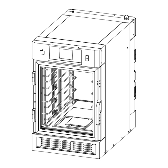
- Page 7 Service Manual for Flextech™ Humidified Holding Cabinet (FTU) MAIN FeATUReS POWER CORD ACTIVE VENT POWER SWITCH WATER INLET TOUCH SCREEN CONTROL PANEL USB DRIVE DOORS & HINGES ARE REVERSIBLE HIGH LIMIT PROTECTOR RACKS FOR 5 SHELVES REMOVABLE SPILLAGE PAN SM-PH-FT-0011 8/27/2014...
-
Page 8: Removal And Replacement Of Parts
Service Manual for Flextech™ Humidified Holding Cabinet (FTU) ReMOVAL AND RePLACeMeNT OF PARTS eLeCTRICAL LOCKOUT/TAGOUT PROCeDURe eSD WRIST STRAP An eSD Wrist Strap is required when replacing certain WARNING components. BEFORE PERFORMING ANY SERVICE THAT 1. Place both of the unit’s power ON/OFF Switches in the INVOLVES ELECTRICAL CONNECTION OR “OFF”... -
Page 9: Covers And Panels
Service Manual for Flextech™ Humidified Holding Cabinet (FTU) COVeRS AND PANeLS FRONT LOWeR LOUVeReD PANeL Before removing any cover or panel that may expose The Front lower louvered Panel provides access to the electrical components or wiring to contact, turn main heating elements. -
Page 10: Side Panels
Service Manual for Flextech™ Humidified Holding Cabinet (FTU) SIDe PANeLS TOP PANeL 1. Place the unit’s Power ON/OFF Switch in the OFF The Top panel gives access to the humidity Vent Fan. position, and follow the proper lockout/Tagout 1. Place the unit’s Power ON/OFF Switch in the OFF procedures. -
Page 11: Control Panel
Service Manual for Flextech™ Humidified Holding Cabinet (FTU) CONTROL PANeL UPPeR ReAR PANeL The Control Panel allows access to the Control Module, ON/ The Upper rear Panel allows access to the Upper rear Off Switch, Power Supply Board, relay Board, Solid State Cooling Fan. -
Page 12: Bottom Panel
Service Manual for Flextech™ Humidified Holding Cabinet (FTU) BOTTOM PANeL UPPeR CAVITY PANeL The Bottom Panel inside the Food holding Compartment There is a removable upper panel inside the Food holding is removable. Cavity. 1. Place the unit’s Power ON/OFF Switch in the OFF 1. -
Page 13: Control Compartment Parts
Service Manual for Flextech™ Humidified Holding Cabinet (FTU) CONTROL COMPARTMeNT PARTS POWeR ON/OFF SWITCH 1. Place the unit’s Power ON/OFF Switch in the OFF CONTROL MODULe position, and follow the proper lockout/Tagout procedures. The Control Module is the user interface mounted to the Control Panel. -
Page 14: Usb Port
Service Manual for Flextech™ Humidified Holding Cabinet (FTU) USB PORT POWeR SUPPLY BOARD The USB Port is mounted to the Control Panel beneath a The Power Supply Board is mounted inside the Control swinging, protective shield. Compartment behind the Control Panel. 1. -
Page 15: Control Board
Service Manual for Flextech™ Humidified Holding Cabinet (FTU) CONTROL BOARD SOLID STATe ReLAYS The Control Board is mounted inside the Control There are 2 Solid State relays mounted inside the Control Compartment behind the Control Panel. Compartment behind the Control Panel. An eSD Wrist Strap (provided in replacement kit) is required 1. -
Page 16: Fuses And Fuse Holder
Service Manual for Flextech™ Humidified Holding Cabinet (FTU) 7. Apply heat transfer compound to mounting surface of FUSeS AND FUSe HOLDeR Solid State relay(s). There are two (2) 12.5 Amp Fuses mounted in a fuse holder inside the Control Compartment behind the Control Panel. 8. -
Page 17: Power Relays
Service Manual for Flextech™ Humidified Holding Cabinet (FTU) POWeR ReLAYS TRANSFORMeR There are 2 Power relays mounted inside the Control There is a 240V/24V 40VA transformer mounted in the Compartment behind the Control Panel. Control Compartment behind the Control Panel. 1. -
Page 18: Buzzer
Service Manual for Flextech™ Humidified Holding Cabinet (FTU) BUZZeR UPPeR ReAR COOLING FAN There is a buzzer located in the Control Compartment behind An Axial Cooling fan is located behind the upper rear panel. the Control Panel. 1. Place the unit’s Power ON/OFF Switch in the OFF position, and follow the proper lockout/Tagout procedures. -
Page 19: Humidity Vent Fan
Service Manual for Flextech™ Humidified Holding Cabinet (FTU) BOTTOM COMPARTMeNT PARTS HUMIDITY VeNT FAN A Squirrel-Cage “Biscuit” Fan is located at the top rear of HIGH LIMIT THeRMOSTAT the unit beneath the Top Panel. A high-limit Thermostat is mounted behind the rear 1. -
Page 20: Water Inlet Solenoid
Service Manual for Flextech™ Humidified Holding Cabinet (FTU) 8. remove high-limit Thermostat from unit. WATeR INLeT SOLeNOID 9. To install replacement high-limit Thermostat, reverse The Water inlet Solenoid is mounted behind the rear these steps. louvered Panel. Note: Do not crush, pinch or kink high-limit Thermostat capillary tube. -
Page 21: Water Regulator
Service Manual for Flextech™ Humidified Holding Cabinet (FTU) 8. Clean all threads. WATeR ReGULATOR 9. Wrap all threads with Teflon tape. The Water regulator is mounted behind the rear louvered 10. Thread replacement Solenoid onto fitting and tighten. Panel. Orient coil vertically and “y” Strainer in the down position. -
Page 22: Bottom Cooling Blower
Service Manual for Flextech™ Humidified Holding Cabinet (FTU) 7. remove regulator from fitting. BOTTOM COOLING BLOWeR A tangential Blower used to circulate air throughout the Adjustment Screw lower part of the unit is located behind the lower rear Panel. 8. Clean all threads. 9. -
Page 23: Humidification Motor
Service Manual for Flextech™ Humidified Holding Cabinet (FTU) 9. Disconnect fitting between Water regulator and HUMIDIFICATION MOTOR humidification Cylinder. A Motor that spins a slinger disc is located under the bottom panel of the food holding compartment. 1. Place the unit’s Power ON/OFF Switch in the OFF position, and follow the proper lockout/Tagout procedures. -
Page 24: Capacitor
Service Manual for Flextech™ Humidified Holding Cabinet (FTU) 13. remove Atomizer Disc. CAPACITOR The Capacitor is located under the bottom panel of the food holding compartment. 1. Place the unit’s Power ON/OFF Switch in the OFF position, and follow the proper lockout/Tagout procedures. - Page 25 Service Manual for Flextech™ Humidified Holding Cabinet (FTU) 9. Disconnect fitting between Water regulator and 15. remove hex nuts securing mounting bracket. humidification Cylinder. 16. remove bracket and capacitor. 10. lift motor pan from unit. 11. invert pan. 12. To remove Capacitor, carefully remove rubber boot to expose terminals.
-
Page 26: Circulating Fan Motor
Service Manual for Flextech™ Humidified Holding Cabinet (FTU) 9. Disconnect fitting between Water regulator and CIRCULATING FAN MOTOR humidification Cylinder. A Circulating Fan is located under the bottom panel of the food holding compartment. Note: This procedure is similar to the removal and replacement of the humidification Motor. -
Page 27: Snap-Disc Thermostat
Service Manual for Flextech™ Humidified Holding Cabinet (FTU) SNAP-DISC THeRMOSTAT BOTTOM PANeL INTeRLOCK SWITCH A Snap-Disc type high-limit Thermostat is located under the An interlock switch that prevents the unit from running when bottom panel of the food holding compartment. the Bottom Panel has been removed is located behind the Front lower Panel. -
Page 28: Humidification System Heating Element Ring
Service Manual for Flextech™ Humidified Holding Cabinet (FTU) 9. rewire Switch. HUMIDIFICATION SYSTeM HeATING eLeMeNT RING Note: Wires are connected to Common (C) and Normally Open (NO) terminals. Connecting any other way will A heating element ring wraps around the humidification prevent the unit from functioning properly. -
Page 29: Ring Temperature Sensor (Rtd)
Service Manual for Flextech™ Humidified Holding Cabinet (FTU) 9. remove Phillips-head screw securing water delivery RING TeMPeRATURe SeNSOR (RTD) tubing and rotate tubing away. An rTD-type Temperature Sensor is located under the bottom panel. 10. loosen clamping bolt on heating element ring and slide 1. - Page 30 Service Manual for Flextech™ Humidified Holding Cabinet (FTU) 8. remove the 9 Phillips-head screws securing the Motor 13. lift Motor Pan from unit. Pan to the unit. 14. invert Motor Pan. 15. remove 2 hex nuts securing ring Temperature Sensor to Motor Pan and remove Sensor.
-
Page 31: Cavity Heating Element
Service Manual for Flextech™ Humidified Holding Cabinet (FTU) 8. From inside food holding compartment, pull heating CAVITY HeATING eLeMeNT element until free of mounting standoffs and remove element from unit. A tubular heating element is used to maintain the food holding compartment temperature. -
Page 32: Left Side Components
Service Manual for Flextech™ Humidified Holding Cabinet (FTU) LeFT SIDe COMPONeNTS 8. remove any remaining sealant from mounting surface. 9. To replace Cavity Temperature Sensor, apply a small CAVITY TeMPeRATURe SeNSOR amount of silicone sealant to flange, mount sensor on studs and secure with hex nuts. -
Page 33: Humidity Sensor
Service Manual for Flextech™ Humidified Holding Cabinet (FTU) DOOR PARTS HUMIDITY SeNSOR The humidity Sensor is used to control the humidification DOOR LATCH System and is located behind the left Side Panel. The unit has a magnetic Door latch mounted to the edge 1. -
Page 34: Door Hinge
Service Manual for Flextech™ Humidified Holding Cabinet (FTU) 6. remove hinge plate and hinge half. DOOR HINGe 7. remove 2 Screws securing each hinge half to unit face. The unit has two hinges on the edge of each of its 2 doors. 1. -
Page 35: Door Gasket
Service Manual for Flextech™ Humidified Holding Cabinet (FTU) DOOR GASKeT 1. Place the unit’s Power Switch in its OFF position. 2. remove the old gasket by pulling it out of the groove in the unit face. 3. Clean groove with a screwdriver or other flat-bladed tool to remove any dirt or gasket pieces. -
Page 36: Adjustments And Calibrations
Service Manual for Flextech™ Humidified Holding Cabinet (FTU) ADJUSTMeNTS AND CALIBRATIONS HINGe ADJUSTMeNT This procedure should be performed when the door no longer DOOR LATCH ADJUSTMeNT contacts the door gasket or after door gasket replacement and may be done in conjunction with Door latch Adjustment. This procedure should be performed when the door no longer contacts the door gasket or after door gasket replacement 1. -
Page 37: Troubleshooting
Service Manual for Flextech™ Humidified Holding Cabinet (FTU) TROUBLeSHOOTING PROBLeM POSSIBLe CAUSe SOLUTION Unit is unplugged Connect plug to correct outlet Power ON/OFF Switch in OFF position Turn ON Power ON/OFF Switch Unit is not ON Supply Circuit Breaker is tripped Reset breaker Power ON/OFF Switch failure replace Power ON/OFF Switch... -
Page 38: Wiring Diagram
Service Manual for Flextech™ Humidified Holding Cabinet (FTU) WIRING DIAGRAM P/N 169694 COIL COIL 8/27/2014 SM-PH-FT-0011... -
Page 39: Customer Assistance
Phone: +86 21 59153525 / 59153526 Fax: 314-231-2460 Fax: +86 21 33600628 service-dispatch@dukemfg.com service.asiapac@dukemfg.com DUKe eMeA - eUROPe, DUKe eMeA – UK, IReLAND MIDDLe eAST, AFRICA, RUSSIA Phone: +44 (0) 1395 234140 Fax: +44 (0) 1395 234154 Duke Manufacturing CR, s.r.o. Na Dlouhem 86 service.emea@dukemfg.com... - Page 40 Service Manual for Flextech™ Humidified Holding Cabinet (FTU) 8/27/2014 SM-PH-FT-0011...
Need help?
Do you have a question about the FLEXTECH FTU-5 and is the answer not in the manual?
Questions and answers