Table of Contents

Subscribe to Our Youtube Channel
Related Manuals for Fronius CU 600t


Summary of Contents for Fronius CU 600t
- Page 1 / Perfect Charging / Perfect Welding / Solar Energy Operating instructions CU 600t CU 600t/MC Cooling unit 42,0426,0224,EN 010-14062021 Fronius prints on elemental chlorine free paper (ECF) sourced from certified sustainable forests (FSC).
-
Page 3: Table Of Contents
Contents Safety rules Explanation of safety notices General Proper use Environmental conditions Obligations of the operator Obligations of personnel Mains connection Protecting yourself and others Noise emission values Danger from toxic gases and vapours Danger from flying sparks Risks from mains current and welding current Meandering welding currents EMC Device Classifications EMC measures... - Page 4 Filling and starting up the cooling unit Filling the cooling unit Starting up the cooling unit CU 600t /MC: Emptying/filling the torch hosepack Operating modes Disconnect the cooling unit from the power source Safety Disconnecting the cooling unit from the power source...
-
Page 5: Safety Rules
Safety rules Explanation of DANGER! safety notices Indicates immediate danger. ▶ If not avoided, death or serious injury will result. WARNING! Indicates a potentially hazardous situation. ▶ If not avoided, death or serious injury may result. CAUTION! Indicates a situation where damage or injury could occur. ▶... -
Page 6: Environmental Conditions
The device is intended solely for the welding processes specified on the rating plate. Any use above and beyond this purpose is deemed improper. The manufacturer shall not be held liable for any damage arising from such usage. Proper use includes: carefully reading and following all the instructions given in the operating instructions studying and obeying all safety and danger notices carefully performing all stipulated inspection and maintenance work. -
Page 7: Protecting Yourself And Others
This may affect a number device types in terms of: Connection restrictions Criteria with regard to the maximum permissible mains impedance Criteria with regard to the minimum short-circuit power requirement at the interface with the public grid see "Technical data" In this case, the plant operator or the person using the device should check whether the device may be connected, where appropriate by discussing the matter with the power supply company. -
Page 8: Danger From Toxic Gases And Vapours
Danger from The fumes produced during welding contain harmful gases and vapours. toxic gases and Welding fumes contain substances that cause cancer, as stated in Monograph 118 of the vapours International Agency for Research on Cancer. Use at-source extraction and a room extraction system. If necessary, use a welding torch with an integrated extraction device. -
Page 9: Risks From Mains Current And Welding Current
Risks from mains An electric shock is potentially life threatening and can be fatal. current and weld- Do not touch live parts either inside or outside the device. ing current During MIG/MAG welding and TIG welding, the welding wire, the wirespool, the feed rollers and all pieces of metal that are in contact with the welding wire are live. -
Page 10: Meandering Welding Currents
Meandering weld- If the following instructions are ignored, meandering welding currents can develop with ing currents the following consequences: Fire hazard Overheating of parts connected to the workpiece Irreparable damage to ground conductors Damage to device and other electrical equipment Ensure that the workpiece is held securely by the workpiece clamp. -
Page 11: Emf Measures
Shielding, if necessary Shield off other nearby devices Shield off entire welding installation EMF measures Electromagnetic fields may pose as yet unknown risks to health: effects on the health of others in the vicinity, e.g. wearers of pacemakers and hear- ing aids wearers of pacemakers must seek advice from their doctor before approaching the device or any welding that is in progress... -
Page 12: Requirement For The Shielding Gas
Hook chains and/or ropes onto all suspension points provided on the load-carrying equipment. Chains and ropes must be at the smallest angle possible to the vertical. Remove gas cylinder and wire-feed unit (MIG/MAG and TIG devices). If the wire-feed unit is attached to a crane holder during welding, always use a suitable, insulated wirefeeder hoisting attachment (MIG/MAG and TIG devices). -
Page 13: Danger From Escaping Shielding Gas
The manufacturer's instructions must be observed as well as applicable national and international regulations for shielding gas cylinders and accessories. Danger from Risk of suffocation from the uncontrolled escape of shielding gas escaping shield- Shielding gas is colourless and odourless and, in the event of a leak, can displace the ing gas oxygen in the ambient air. -
Page 14: Commissioning, Maintenance And Repair
Before switching on the device, ensure that no one is likely to be endangered. Check the device at least once a week for obvious damage and proper functioning of safety devices. Always fasten the shielding gas cylinder securely and remove it beforehand if the device is to be transported by crane. -
Page 15: Disposal
(e.g. relevant product standards of the EN 60 974 series). Fronius International GmbH hereby declares that the device is compliant with Directive 2014/53/EU. The full text on the EU Declaration of Conformity can be found at the follow- ing address: http://www.fronius.com... -
Page 16: General
Torch hosepack emptying and filling function as standard ("dry" torch body change - coolant cannot get into the interface) CU 600t MV /MC (multivoltage/MultiControl version) for single-shift operation and for multivoltage operation The coolant pump and fan are switched on and off automatically as standard. The... -
Page 17: Scope Of Supply
Scope of supply The scope of supply comprises: Cooling unit 5 l coolant in a canister Four 5x25 mm self-tapping screws Operating Instructions Also included with the MultiControl version: 0.7 m gas hose T gas splitter Validity of "Gen- With regard to cooling units, the "General Delivery and Payment Conditions" according to eral Delivery and the price list only apply under the following conditions: Payment Condi-... -
Page 18: Warning Notices On The Device
Warning notices The cooling unit is fitted with safety symbols and a rating plate. The rating plate and on the device safety symbols must not be removed or painted over. The symbols warn against operat- ing the equipment incorrectly, as this may result in serious injury and damage. Welding is dangerous. - Page 19 Do not use the functions described here until you have fully read and understood the fol- lowing documents: This document All documents relating to the system components, especially the safety rules Do not dispose of used devices with domestic waste. Dispose of them according to the safety rules.
-
Page 20: Options
Options OPT/i CU flow The OPT/i CU flow temperature sensor option offers monitoring of the coolant temperat- temperature ure and flow rate. sensor Coolant temperature monitoring and flow monitoring are parts of an installation set and cannot be ordered separately. Coolant temperature monitoring A temperature sensor monitors the coolant return temperature during welding. -
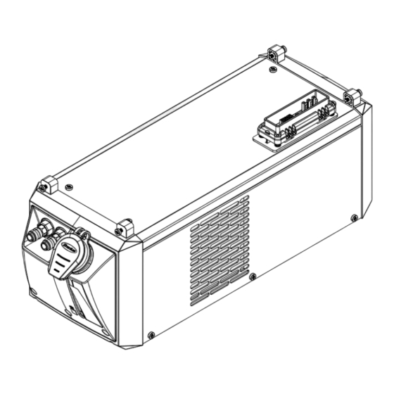
Page 21: Connections And Mechanical Components
Power source connection Coolant viewing window Important notes on maintenance and operation Fuse holder (only on CU 600t MV and CU 600t MV /MC) Blanking cover for CU 600t and CU 600t /MC Rating plate Opening for turning the coolant pump shaft... -
Page 22: Before Installation And Commissioning
Before installation and commissioning Safety WARNING! Danger due to incorrect operation and incorrectly performed work. This can result in severe personal injury and damage to property. ▶ All the work and functions described in this document must only be carried out and used by trained and qualified personnel. -
Page 23: Information About The Coolant
Information about The cooling unit is delivered empty. the coolant Use only original Fronius coolant (Cooling Liquid FCL 10/20 or torch coolant) when filling the cooling unit. Other coolants are not recommended for electrical conductivity and material compatibility reasons. Guarantee provi- The coolant pump may only be used with original coolant supplied by the manufacturer. -
Page 24: Fitting The Cooling Unit To The Trolley
Fitting the cooling unit to the trolley General The welding system can be fitted to a trolley to make the system (incl. cooling unit) more mobile. CAUTION! Risk due to work that has been carried out incorrectly. This can result in serious damage to property ▶... -
Page 25: Connecting The Cooling Unit To The Power Source
Connecting the cooling unit to the power source Safety WARNING! Danger from electric current. An electric shock can be fatal. ▶ Turn the power source mains switch to the "O" position. ▶ Disconnect the power source from the mains. ▶ Ensure that the power source remains disconnected from the mains until all work has been completed. - Page 26 NOTE! Screws are supplied with the cooling unit. Only with MultiControl versions: 0.7 m gas hose in MC cooling unit scope of supply For gas supply max. 20 l/min. Gas flow rate on the pressure regulator/max. 4 bar max. 20 l/Min.*** max.
-
Page 27: Connect The Coolant Hoses To The Cooling Unit
Connect the coolant hoses to the cooling unit Safety WARNING! Danger from electric current. An electric shock can be fatal. ▶ Turn the power source mains switch to the "O" position. ▶ Disconnect the power source from the mains. ▶ Ensure that the power source remains disconnected from the mains until all work has been completed. -
Page 28: Filling And Starting Up The Cooling Unit
Filling and starting up the cooling unit Filling the cool- WARNING! ing unit An electric shock can be fatal. Before starting the work described below: ▶ Turn the power source mains switch to the "O" position ▶ Disconnect the power source from the mains ▶... -
Page 29: Starting Up The Cooling Unit
3 minutes The operating status of the cooling unit can be manually changed by selecting different operating modes. CU 600t /MC: When using a MultiControl cooling unit, the "Empty/fill torch hosepack" setup parameter Emptying/filling... -
Page 30: Operating Modes
After the torch body has been successfully changed, the torch hosepack can be filled with coolant. NOTE! Procedure for filling long torch hosepacks (> 4 m, extension hosepacks): ▶ Connect the hosepack/extension hosepack to the power source ▶ Fill the coolant tank to the maximum ▶... -
Page 31: Disconnect The Cooling Unit From The Power Source
Disconnect the cooling unit from the power source Safety WARNING! Danger from electric current. An electric shock can be fatal. ▶ Turn the power source mains switch to the "O" position. ▶ Disconnect the power source from the mains. ▶ Ensure that the power source remains disconnected from the mains until all work has been completed. - Page 32 CAUTION! Risk of injury and damage due to short- circuiting of the cooling unit connec- tion on the underside of the power source. Dirt and damage can cause short circuits on the cooling unit connection. After dis- mantling the power source, always close the cooling unit connection cover (1) on the underside of the power source.
-
Page 33: Fitting The Coolant Filter Option
Fitting the coolant filter option Safety WARNING! Danger from electric current. An electric shock can be fatal. ▶ Turn the power source mains switch to the "O" position. ▶ Disconnect the power source from the mains. ▶ Ensure that the power source remains disconnected from the mains until all work has been completed. -
Page 34: Troubleshooting
Troubleshooting Safety WARNING! Danger due to work that has been carried out incorrectly. This can result in serious injury and damage to property. ▶ All the work described below must only be carried out by trained and qualified per- sonnel. ▶... - Page 35 Insufficient or no coolant flow Cause: Coolant level too low Remedy: Top up coolant Cause: Constriction or foreign body in cooling circuit Remedy: Remove constriction or foreign body Cause: Coolant contaminated Remedy: Change the coolant and then bleed the cooling unit Cause: Coolant filter (option) misplaced when connecting coolant return Remedy:...
- Page 36 The welding torch becomes very hot Cause: The specification of the cooling unit is inadequate Remedy: Observe the duty cycle and loading limits Cause: The specification of the welding torch is inadequate Remedy: Observe the duty cycle and loading limits Cause: Inadequate coolant flow Remedy:...
-
Page 37: Twisting The Coolant Pump Shaft
Twisting the coolant pump shaft Safety WARNING! Danger due to work that has been carried out incorrectly. This can result in severe personal injury and damage to property ▶ All the work described below must only be carried out by trained and qualified per- sonnel. -
Page 38: Care, Maintenance And Disposal
Care, maintenance and disposal Safety WARNING! Danger due to work that has been carried out incorrectly. All the work described below must only be carried out by trained and qualified personnel. ▶ Fully read and understand this document. ▶ Fully read and understand all the Operating Instructions for the system components, especially the safety rules. -
Page 39: Symbols For Care And Maintenance Of The Cooling Unit
If water-cooled system components are operated without coolant, this will nor- mally result in the failure of the system components. Fronius shall not be liable for any damage resulting from such action. In addition, no war- ranty claims will be entertained. -
Page 40: Blowing Out The Cooler
Every 24 months in single-shift operation with FCL 10/20 coolant Change the coolant NOTE! The maintenance work is described over the following pages. Blowing out the cooler NOTE! For the sake of clarity, the cooling unit is shown in the following figures without the power source. - Page 41 NOTE! The coolant must not be disposed of in the public sewage system. Dispose of coolant in accordance with the applicable local and national regulations. NOTE! Use only original coolant from the manufacturer when refilling the cooling unit. NOTE! Seal off the coolant hose as soon as it is pulled out of the coolant pump con- nection.
- Page 42 Ensure that all hose connections are properly established and are not leaking Ensure that there is no coolant inside the device or on its exterior...
-
Page 43: Disposal
Disposal Dispose of in accordance with the applicable national and local regulations. -
Page 44: Technical Data
Ambient temperature Delivery head Flow rate Q (l/min) - The flow rate Q depends on the length of the interconnecting hosepack and the diameter of the hose. CU 600t Supply voltage 1 x 230 V AC (-10% / +15%) 50 / 60 Hz Current consumption 1.2 A... -
Page 45: Cu 600T /Mv
CU 600t /MV Supply voltage 1 x 120 / 230 V AC (-10% / +15%) 50 / 60 Hz Current consumption 2.4 A / 1.2 A Cooling power at Q = 1 l/min + 25 °C (77 °F) 600 W Q = 1 l/min + 40 °C (104 °F) -
Page 46: Cu 600T /Mc
CU 600t /MC Supply voltage 1 x 230 V AC (-10% / +15%) 50 / 60 Hz Current consumption 1.2 A Cooling power at Q = 1 l/min + 25 °C (77 °F) 600 W Q = 1 l/min + 40 °C (104 °F) 400 W Q = max. -
Page 47: Cu 600T Mv /Mc
CU 600t MV /MC Supply voltage 1 x 120 / 230 V AC (-10% / +15%) 50 / 60 Hz Current consumption 2.4 A / 1.2 A Cooling power at Q = 1 l/min + 25 °C (77 °F) 600 W Q = 1 l/min + 40 °C (104 °F) - Page 48 FRONIUS INTERNATIONAL GMBH Froniusstraße 1 A-4643 Pettenbach AUSTRIA contact@fronius.com www.fronius.com Under www.fronius.com/contact you will find the addresses of all Fronius Sales & Service Partners and locations...
Need help?
Do you have a question about the CU 600t and is the answer not in the manual?
Questions and answers